

Antenna for mobile wireless communications and portable-type wireless apparatus using the same
a mobile wireless communication and portable wireless technology, applied in the field of antennas for mobile wireless communications, can solve problems such as deterioration of radio frequency characteristics
- Summary
- Abstract
- Description
- Claims
- Application Information
AI Technical Summary
Problems solved by technology
Method used
Image

Examples
first embodiment
Hereinafter, an antenna for mobile wireless communications in a first embodiment of the present invention will be described with reference to the accompanied drawings.
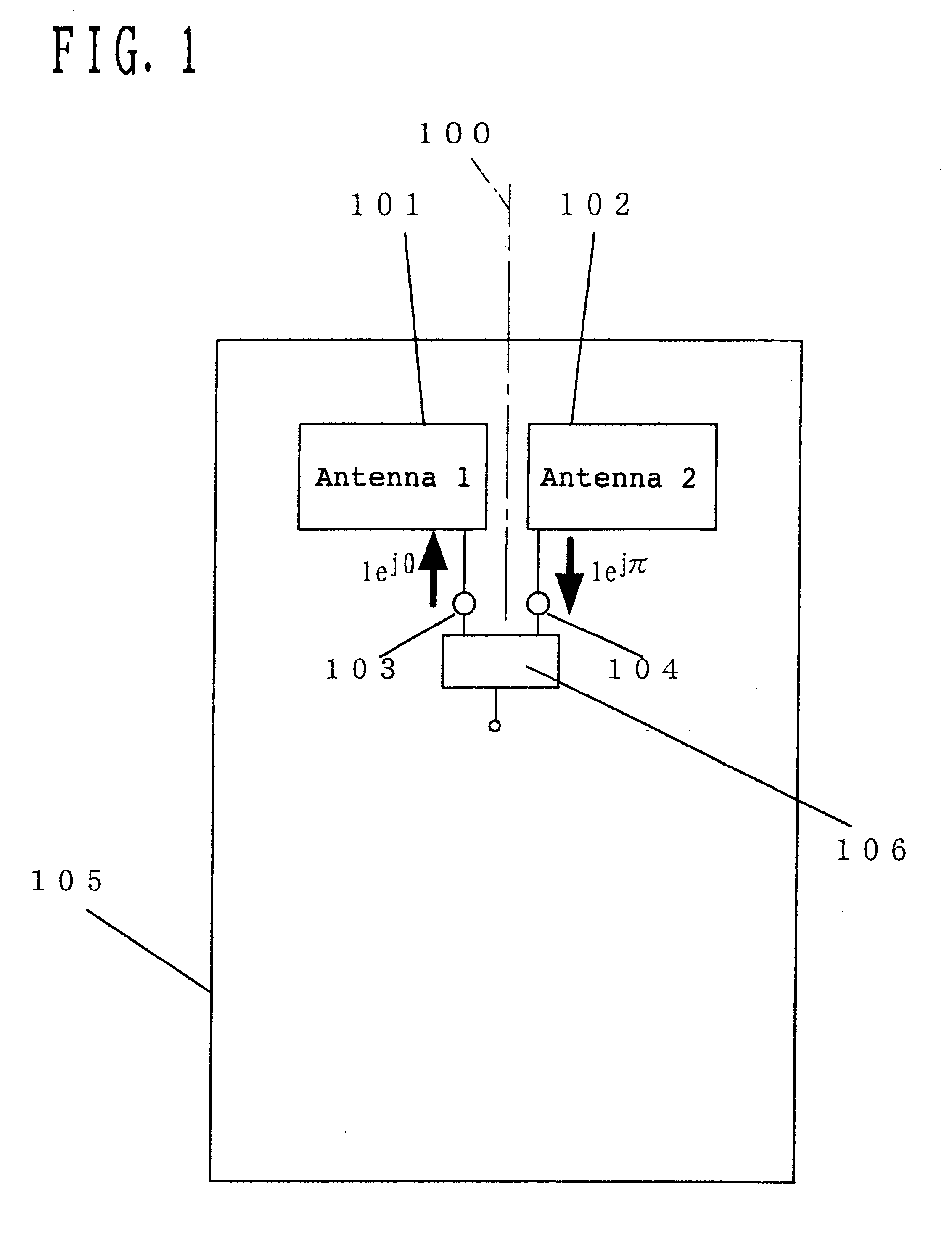
FIG. 1 abstractly shows a circuit diagram of the antenna for mobile wireless communications in the first embodiment of the present invention.
In FIG. 1, 101, 102 are built-in antennas, 103 is a feeding point of 101, 104 is a feeding point of the antenna 102 and 105 is a conductive ground plate. 101 and 102 are of a bisymmetric shape and arranged axi-symmetrically (a reference line 100 in the drawing serves as an axis of symmetry) on the conductive ground plate 105. Also, these antennas 101, 102 are fed substantially at the same amplitude and moreover substantially at the same phase difference of 180 degrees. For example, in the case where a feeding is made from an unbalanced line such as a coaxial cable or the like, a balanced-to-unbalanced conversion circuit 106 as shown in FIG. 1 is used.
A drawing concretely showing t...
second embodiment
Next, an antenna for mobile wireless communications in a second embodiment of the present invention will be described with reference to the accompanied drawings.
The abstract circuit diagram of the present embodiment is the same with FIG. 1. FIG. 4 shows a concrete circuit diagram of the antenna for mobile wireless communications in the second embodiment of the present invention.
In FIG. 4, the same reference numerals with FIG. 2 are used for the same components with the first embodiment and, therefore, the description thereof is omitted.
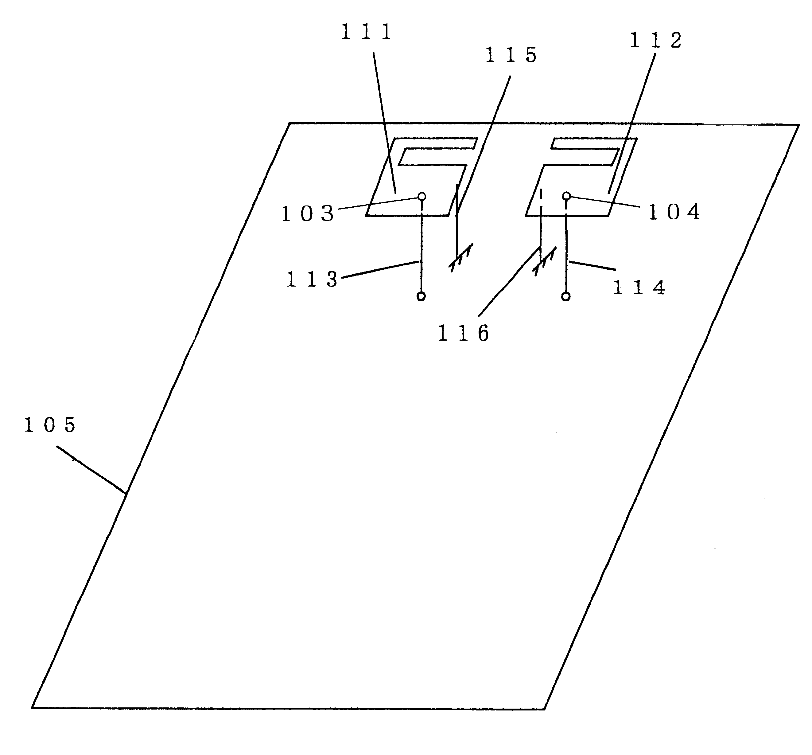
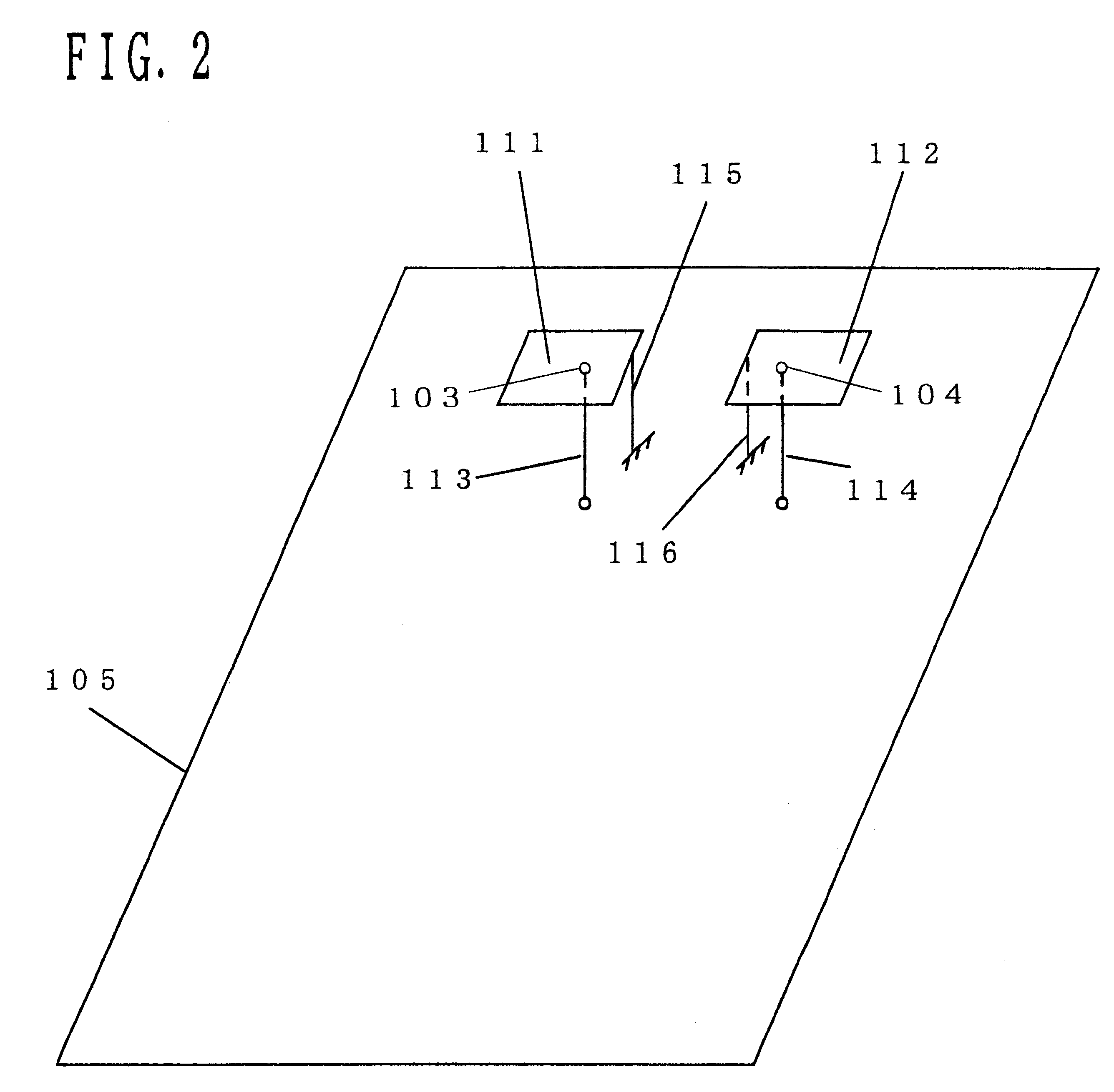
The present embodiment is different from the first embodiment in that if the ambient length of the antenna element 111 forming an antenna 1 is represented by a and the ambient length of the antenna element 112 forming an antenna 2 by b, the length of a and b is different with each other.
The antennas of the present embodiment resonate with the wavelengths corresponding to the lengths substantially two times the ambient lengths of the antenna elements.
A...
third embodiment
Next, an antenna for mobile wireless communications in the third embodiment of the present invention will be described with the accompanied drawings.
The abstract circuit diagram of the present embodiment is the same with FIG. 1. FIG. 5 shows a concrete circuit diagram of the antenna for mobile wireless communications in the third embodiment of the present invention. In FIG. 5, the same reference numerals are used for the same components with the first embodiment and, therefore, the description thereof is omitted.
The present embodiment is different from the first and the second embodiments in that the antenna elements 111, 112 are configured by having a slit in the metal plate of a polygon shape. The antennas of the present embodiment also resonate at the frequencies corresponding to the wavelengths substantially two times the ambient lengths. Accordingly, with the structure made in such manner as the present embodiment, a miniaturization can be effected even if the antennas resonati...
PUM
 Abstract
Description
Claims
Application Information