Tool and method for sheathing of cables

Inactive Publication Date: 2003-04-22
FEDERAL MOGUL SYST PROTECTION GRP SAS
View PDF21 Cites 12 Cited by
  • Summary
  • Abstract
  • Description
  • Claims
  • Application Information

AI Technical Summary

Benefits of technology

In like manner, the possibility of mechanising the application of the sheathing bundle of cables constitutes a major advantage of the invention.
The tool of this invention similarly improves safety in use for its user by preventing the user from touching the possibly sharp edges of the sheath to be fitted, and this constitutes an additional advantage of the invention.
Finally, its suitability for different types of sheaths, such as split ringed plastic sheathing, textiles etc, constitutes another advantage of the device according to the invention.
It will be understood that this arrangement also allows for the tool to be used on cables where the two extremities are fixed, and similarly to ensure the clearance of branches of cables without having to separate the tool from the sheath or from the cables to be sheathed. It therefore provides a good answer to problems caused by known tools constituting the state of the art. Such an implementation guarantees that cables which have a tendency because of their own mechanical structure to remain grouped around their axis, will not spontaneously come out of the tool during an insertion / sheathing operation. Consequently, their extraction or introduction (via the lateral passage) will remain very simple for the user.
The reduction in friction obtained by treating the surface of the parts of the tool exposed to sliding friction, and preferably by having a small angle between the axis of the cables and the axis of the sheath contributes to the particularly advantageous implementation of the invention in automated form.

Problems solved by technology

This tool, however, is limited to use with cables of which one extremity at least is free.
It does not therefore apply to cables which are already laid and which have their two extremities fixed, and it does not, moreover, allow passage of the sheath over branches from the bundle of strands.
Bridging over of fittings or connectors presupposes making them pass into and through the orifice of the shuttle, which consequently then has to be oversized to accommodate them.
A similar tool is shown in U.S. Pat. No. 4,593,442 but wherein the guide head, which extends through a longitudinal slit of the tubing, is formed in two separable grooved parts which co-operate to define an enclosed feed duct; the ability to split the guide head permits on the tool to be applied to, or separated from, a partially sheathed item without access to the end of the item, but such tool assembly / disassembly is not a trivial operation and not suited to a frequently necessary production step.
It is apparent that this technique is hardly efficient if numerous branches or numerous connectors are present in the network to be sheathed.
Moreover, this technique brings risk of injury to the user on the edges of a non-fabric split sheath, such as a plastic ringed sheath, or of pinching electric wires of small diameter by the jaws of the tool.
This arrangement brings the main inconvenience that the wires are subject to little guidance, can easily come out of the sheathing.

Method used


Image

  • Tool and method for sheathing of cables
  • Tool and method for sheathing of cables
  • Tool and method for sheathing of cables

Examples


Embodiment Construction

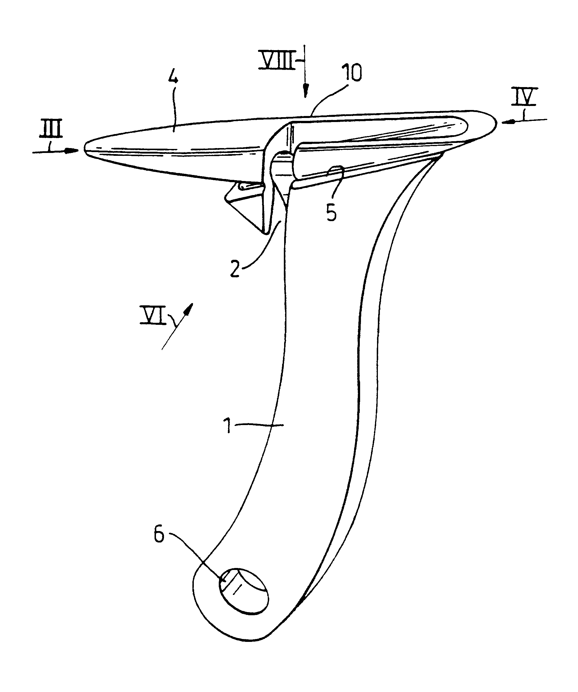
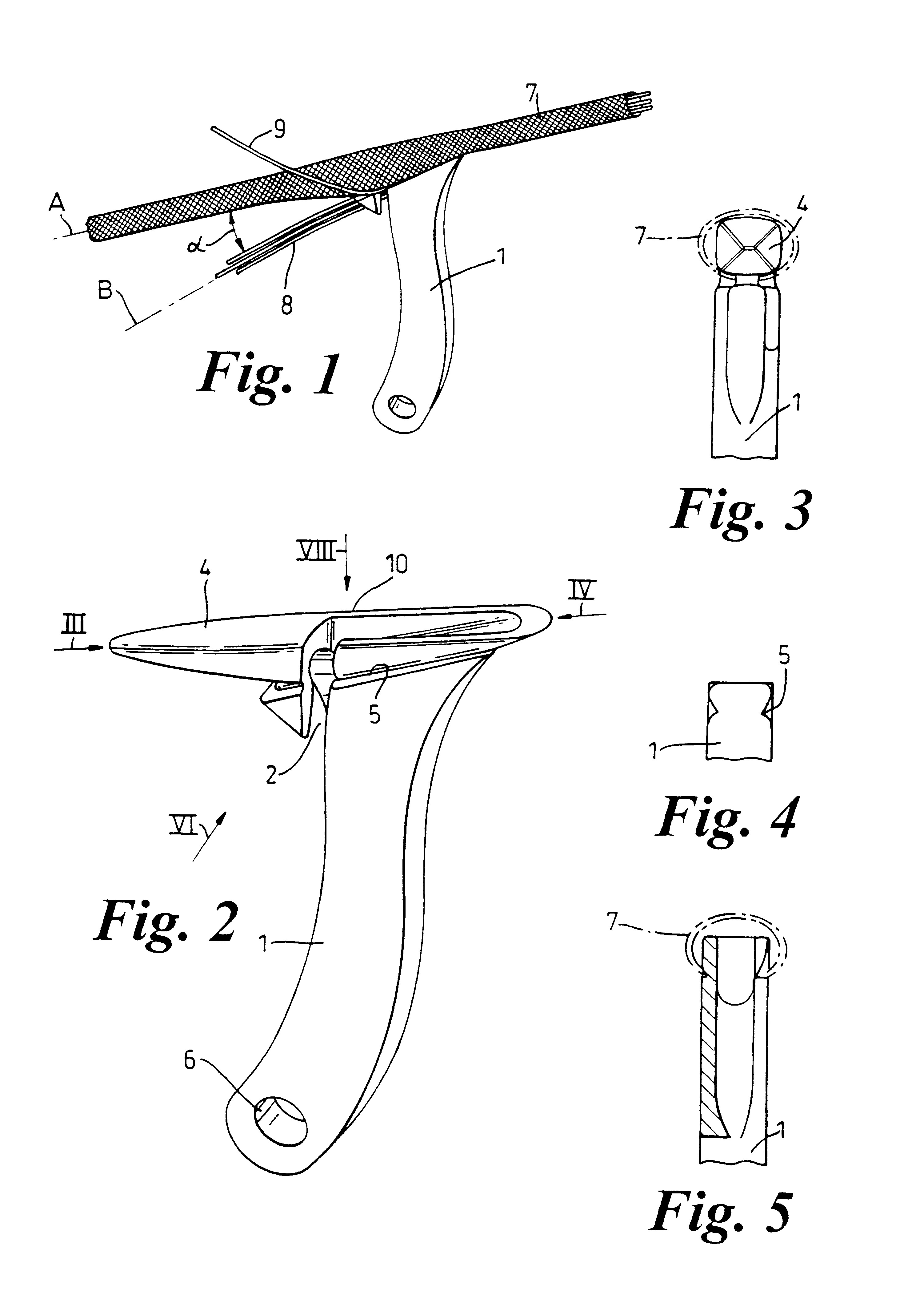
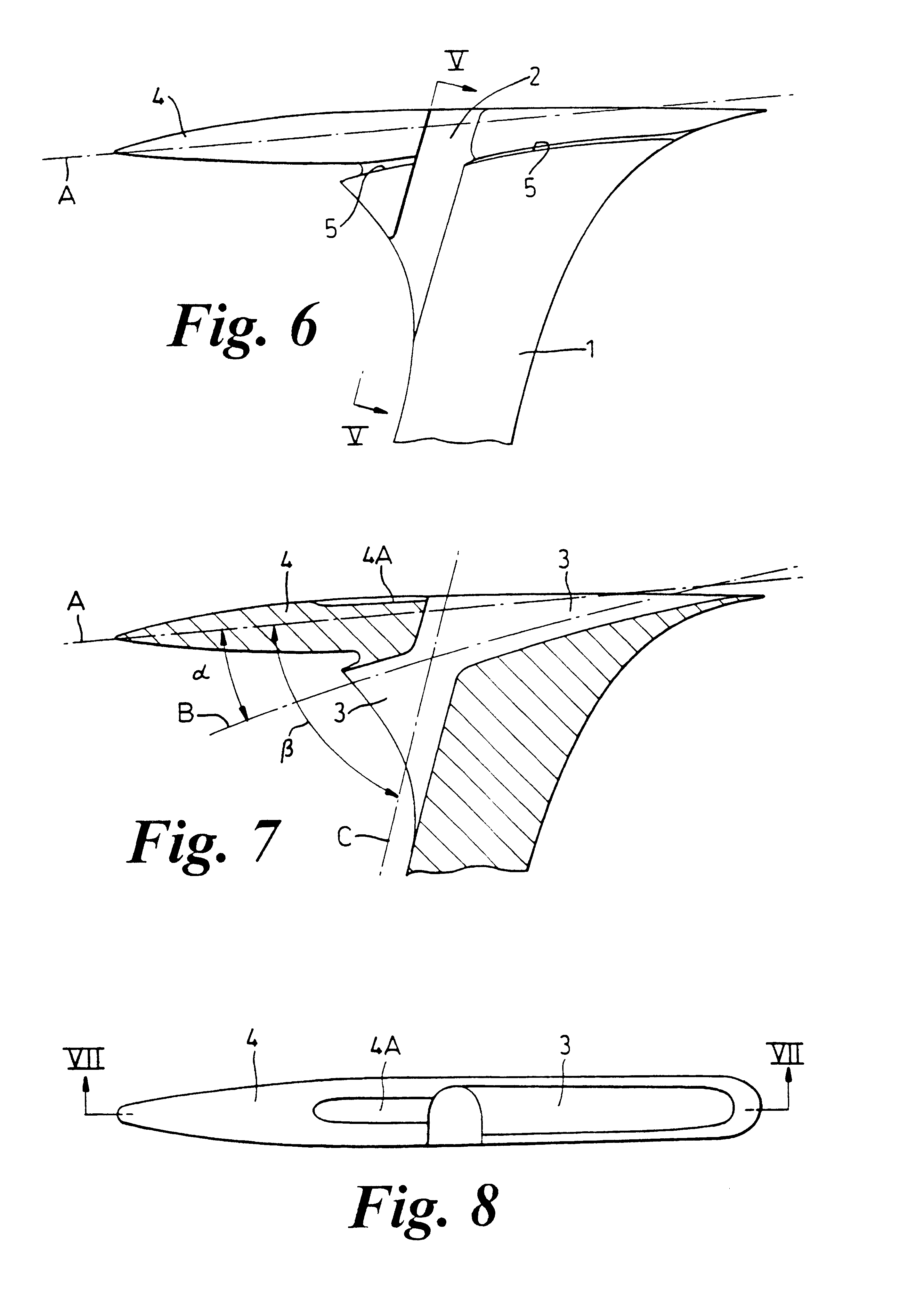
As shown by FIG. 1, the device during use only has one gripping handle 1, by which the user communicates movement forward relative to the tool with regard to a bundle of cables 8, 9 in order to position them on the inside of a sheath 7. For the rest of this description, the terms `in front of the tool` and `behind the tool` will be used with reference to the relative direction of movement with regard to the sheath which is to be put on. As illustrated in FIG. 1, the angle .alpha., formed between and an Axis A of the head of the tool, and the main direction of movement of the sheath on axis B for passage of the bundle of cables, is relatively small, of the order of 20.degree..

In more detail, as seen in FIG. 2, the device comprises two components which are the gripping handle 1 and sheath head 10. For a high degree of robustness, the device is preferably made in only one part, for example from aluminium, by methods known to the expert. It can be made by starting-from a block of alumin...


PUM

PropertyMeasurementUnit
Angleaaaaaaaaaa
Lengthaaaaaaaaaa
Stiffnessaaaaaaaaaa

Abstract

The device is a tool for placing a split sheath around elongated items such as bundles of electronic cables. It comprises a guide bush which makes possible the opening of the sheath, a duct for the cables to be sheathed, lateral grooves for guiding the open sheath and is characterized by the presence of a lateral opening which allows the introduction or extraction of cables possibly already fixed at their two extremities during the use of the tool, as well as by the angle which there is between this opening and the duct for the cables in a manner to keep them in position in the tool be their own rigidity. The tool may have a handle for manipulation and for setting the tool in relative motion along the cables to be sheathed. The invention is also directed at the method for using the tool.

Description

This invention relates to tools for installing generally tubular sheathing, such as split ringed sheathing, around elongated items, such as bundles of electric cables. Nowadays, many types of tool are known for the application of such sheathing.BACKGROUND OF INVENTIONOne type of tool consists of a simple shuttle with a guide head which makes it possible to open the sheathing and an orifice into which are passed the cables to be sheathed. This tool, however, is limited to use with cables of which one extremity at least is free. It does not therefore apply to cables which are already laid and which have their two extremities fixed, and it does not, moreover, allow passage of the sheath over branches from the bundle of strands. Bridging over of fittings or connectors presupposes making them pass into and through the orifice of the shuttle, which consequently then has to be oversized to accommodate them. Such a tool type is shown in JP-A-5742007 (Patent Abstracts of Japan Vol 6. No 112)...

Claims


Application Information

Patent Timeline
IPC IPC(8): H02G1/08H01B13/26H01B13/012
CPCH02G1/08H02G1/085Y10T29/53283Y10T29/53243Y10T29/53652Y10T29/53257Y10T29/53657Y10T29/49123Y10T29/5186Y10T29/5193Y10T29/49194Y10T29/53239Y10T29/5187
Inventor FERRAND, JEAN HENRI
Owner FEDERAL MOGUL SYST PROTECTION GRP SAS
Why Eureka
Try Eureka