Adjustable speed ball bearing jump rope

a technology of ball bearings and jump ropes, which is applied in the field of jump ropes, can solve the problems of reducing the play value unable to easily adjust the length of the jump rope or the speed at which the unable to achieve the adjustment of the speed at which the jump rope can be rotated, so as to improve the play value and longevity of the jump rope, and achieves effective and inexpensive cure

Inactive Publication Date: 2003-04-22
BEAVER TERRY L
View PDF8 Cites 59 Cited by
  • Summary
  • Abstract
  • Description
  • Claims
  • Application Information

AI Technical Summary

Benefits of technology

As will be seen from the annexed drawings and the description herein, the present invention provides a simple and efficient design of jump rope which effectively and inexpensively cures the deficiencies inherent in prior art jump ropes. Modern materials such as plastic covered flexible wire ropes are utili...

Problems solved by technology

In each of the latter, the use of a ball bearing attachment obviates earlier problems of the rope twisting against the handle or the users' hand which diminishes the play value of the jump rope.
And while both of these...

Method used


Image

  • Adjustable speed ball bearing jump rope
  • Adjustable speed ball bearing jump rope
  • Adjustable speed ball bearing jump rope

Examples


Embodiment Construction

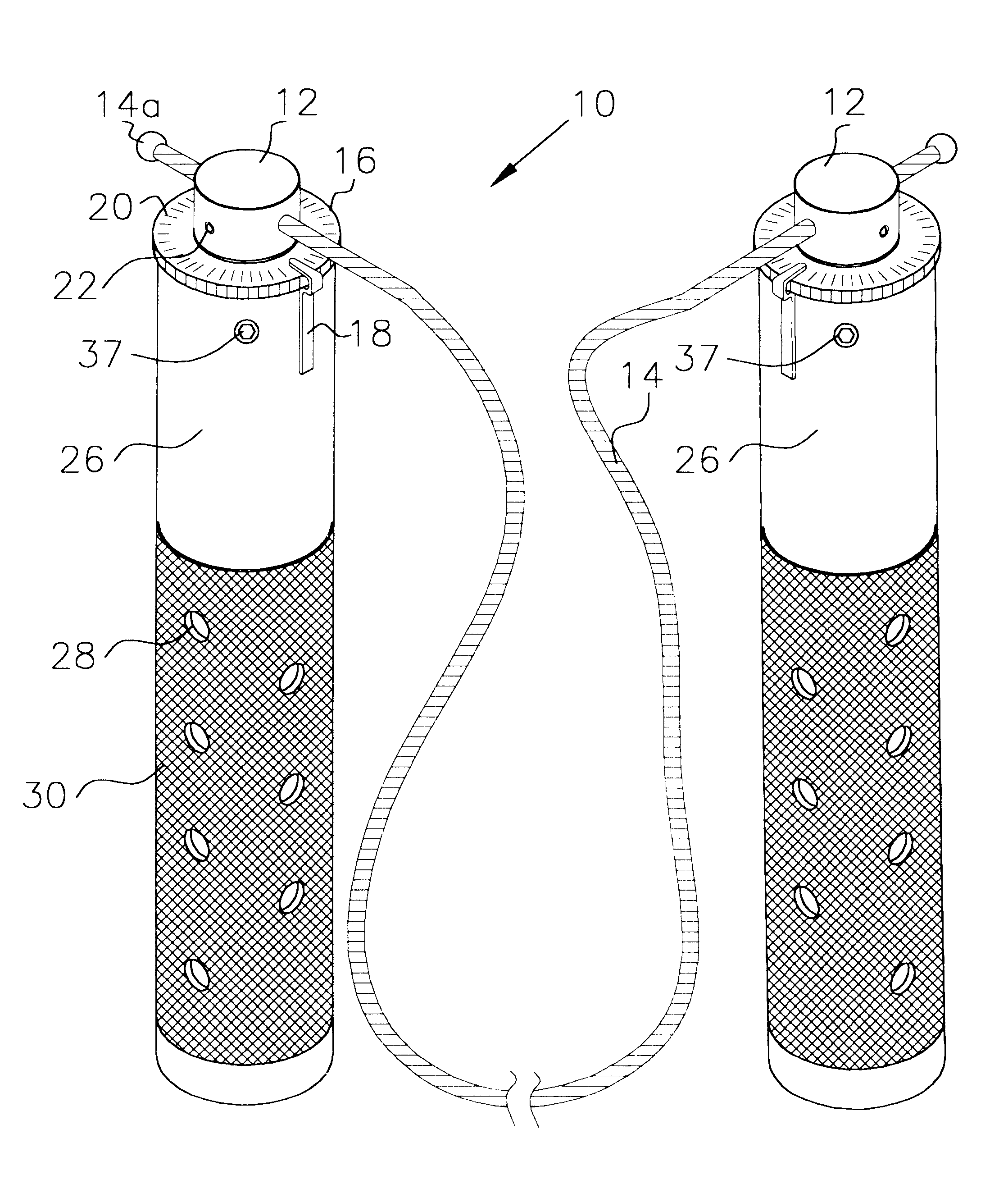
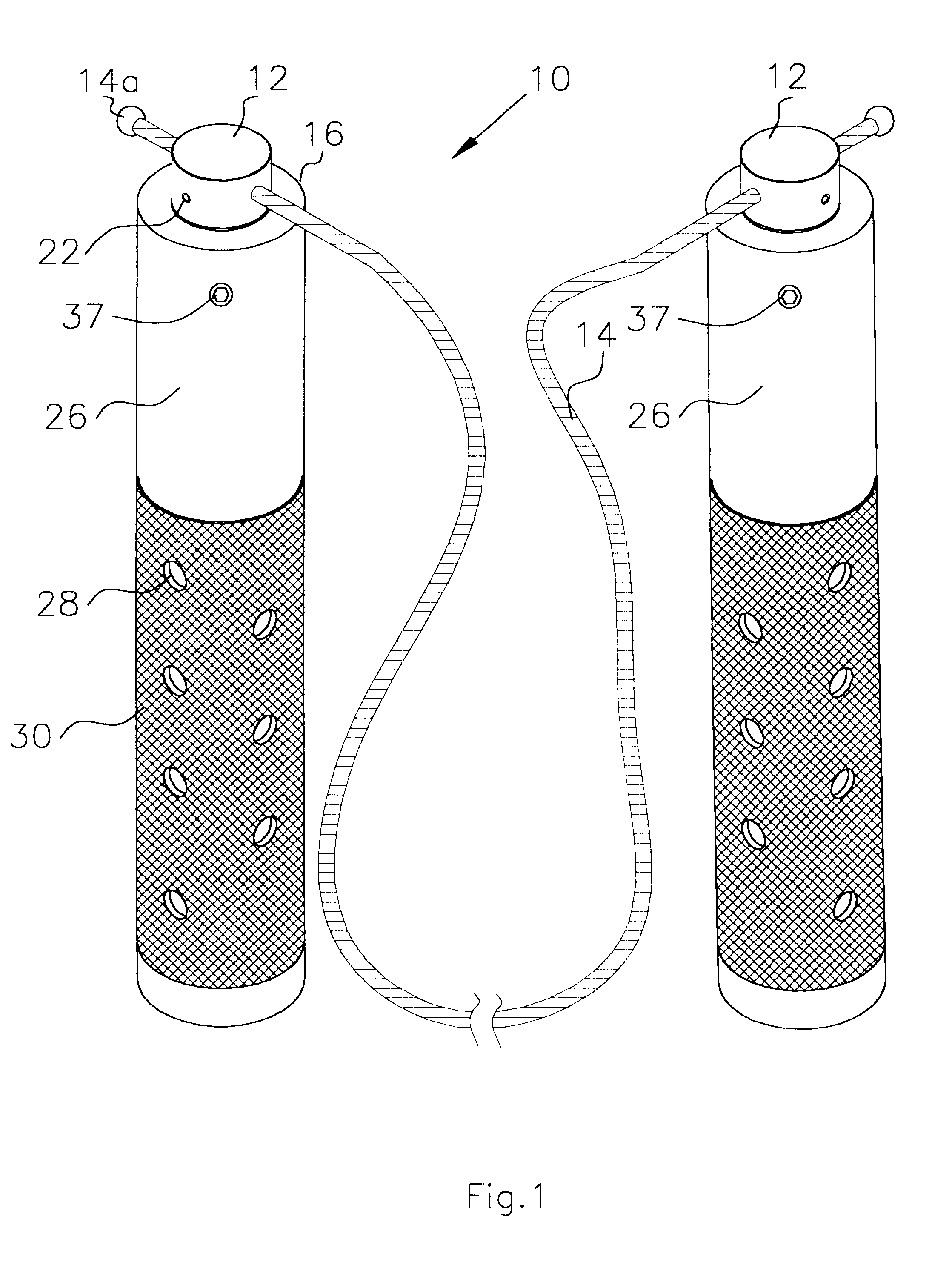
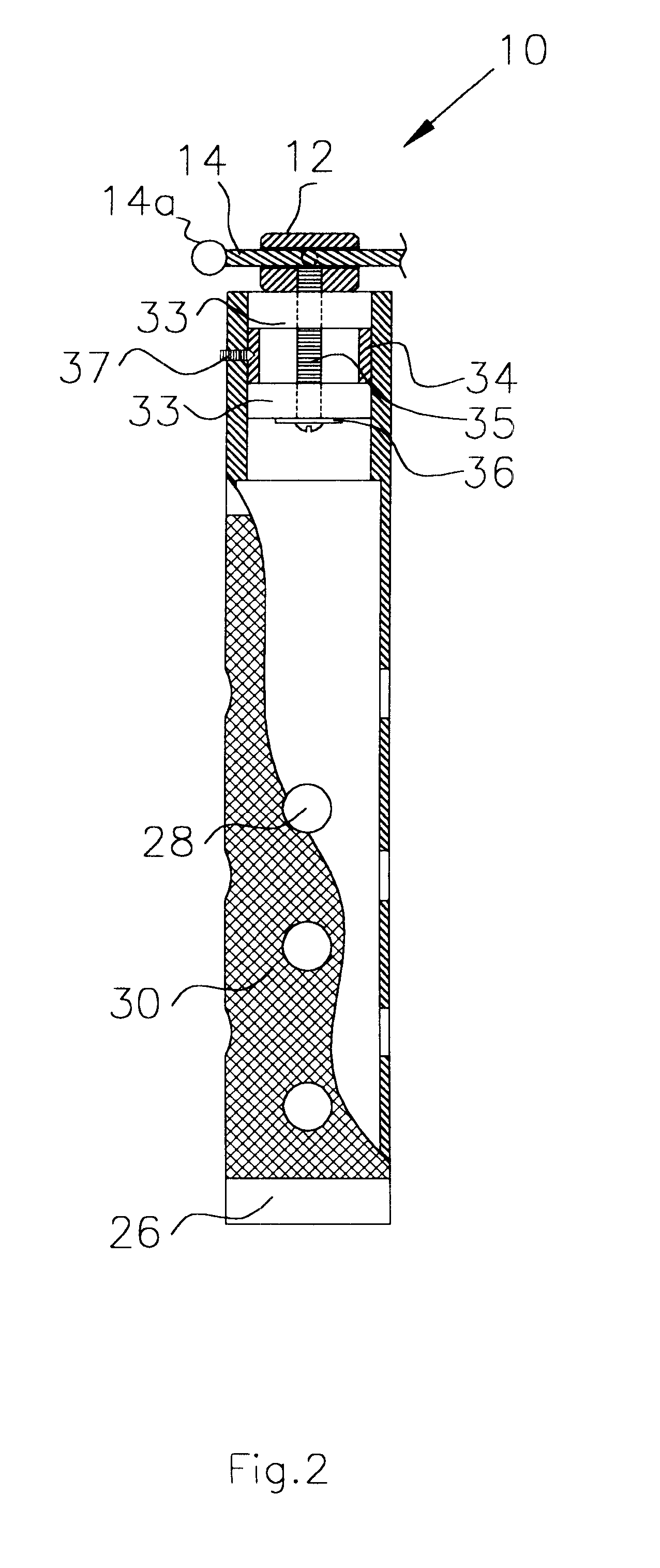
Referring now to the drawings wherein like numerals correspond to like and corresponding parts throughout the several views, the invention is designated overall by the numeral 10. In FIG. 1, rope 14 extends between handles 26 through boss' 12. Rope end 14a stops rope 14 from accidentally dislodging when crimp screw 22 is undone. Vent holes 28 and knurled grip surface 30 provide comfort and cooling during use. Bearing assemblies 33 (FIG. 2) are retained in place with set screw 37 bearing against spacer 14. Screw bolt 35 holds the assembly of the two bearings 33, separated by spacer 34, and boss 12. The washer 36 attaches the two inner races of bearing assemblies 33 and boss 12 to provide the rotation of the rope 14 around the axis of screw bolt 35 when being used for jumping.

FIGS. 3 and 4 disclose a second embodiment having an identical bearing assembly as the first embodiment. In addition, the second embodiment includes a friction braking system to retard the speed of rotation when ...


PUM


Abstract

A speed ball bearing jump rope construction with an adjustable rope length, the invention consisting of a pair of hollow handles having external grip surfaces, vent holes and a bearing assembly at one end of each handle fastened with a screw threaded into the handles. Screws mounted within each of the tops of the bearing assemblies permit the rope to slide to shorten the length.

Description

BACKGROUND OF THE INVENTION.This invention relates primarily to jump ropes and more particularly to jump ropes using a ball bearing assembly connecting the rope to the handle.While the structure of jump ropes has improved over the years from the beginning models which feature a simple rope. More sophisticated structures were then provided wherein a simple handle was tied or otherwise crudely attached to each end of the rope. More recently jump rope manufacturers have advertised and sold more sophisticated models having a variety of ball bearing attachments between the rope and the handle such as those disclosed in U.S. Pat. No. 4,101,123 issued to Anthony Jul. 18, 1978 and U.S. Pat. No. 5,749,812 issued to Feciura and Lee on May 12, 1998. In each of the latter, the use of a ball bearing attachment obviates earlier problems of the rope twisting against the handle or the users' hand which diminishes the play value of the jump rope. And while both of these inventions were vast improvem...

Claims


Application Information

Patent Timeline
IPC IPC(8): A63B5/20A63B5/00
CPCA63B5/20A63B2225/09A63B2208/12
Inventor BEAVER, TERRY L.
Owner BEAVER TERRY L
Why Eureka
Try Eureka