High power pin diode switch

a high-power, pin-diode technology, applied in the field of microwave switches, can solve the problems of many limitations, pin-diode speed is relatively slow in comparison to regular diodes,

Inactive Publication Date: 2003-04-22
RAYTHEON CO
View PDF6 Cites 43 Cited by
  • Summary
  • Abstract
  • Description
  • Claims
  • Application Information

AI Technical Summary

Problems solved by technology

The earliest switches used in microwave applications were mechanical switches, but they suffered from many limitations.
The intrinsic layer has a relatively long recovery time that causes PIN diodes to be relatively slow in comparison to regular diodes.
U.S. Pat. No. 4,267,538 to Assal, et al. teaches a multiport PIN diode switch, but it is concerned with achieving optimal impedance matching between its various input and output ports and not with high power switching problems.

Method used


Image

  • High power pin diode switch
  • High power pin diode switch
  • High power pin diode switch

Examples


Embodiment Construction

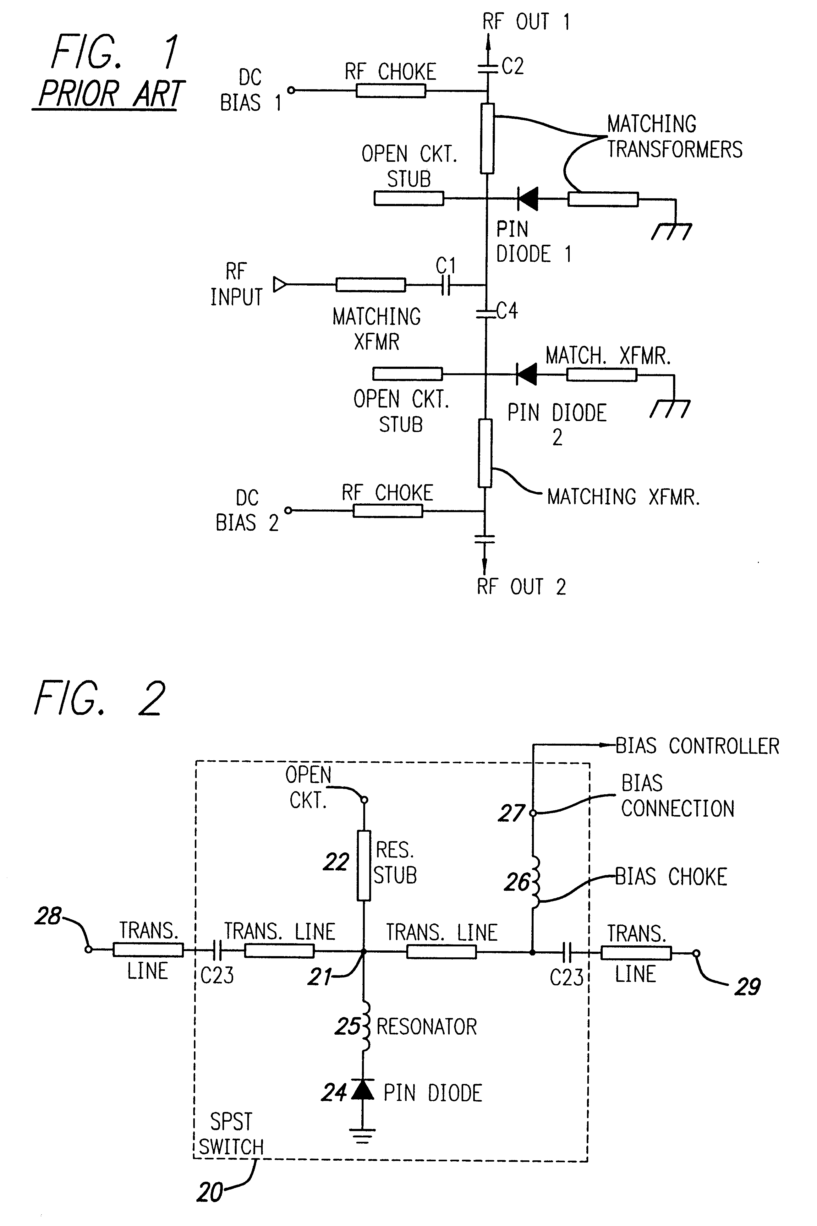
Illustrative embodiments and exemplary applications are described below with reference to the accompanying drawings to disclose the advantageous teachings of the present invention. Referring now to the drawings wherein the reference numerals designate like elements throughout, FIG. 1 shows the prior art SPDT PIN diode switch described in U.S. Pat. No. 5,109,205 mentioned above. This is a millimeter wave shunt-mounted switch designed to couple an RF input to one or the other of a pair of outputs, where first and second bias supplies are used to control the on / off state of the PIN diodes. When a diode is forward biased, it presents a low loss to RF energy but, when reverse biased, affords a high impedance. Thus, for example, if the DC biases #1 and #2 are such that the PIN diode 1 is forward biased, while PIN diode 2 is reverse biased, the RF output will appear at output #2 because output #1 is effectively held at RF ground potential. On the other hand, if the bias is such that diode ...


PUM


Abstract

A high power PIN diode single pole double throw (SPDT) switch for use in radar systems transmitting at over 50 watts of power. These systems require a switch that will provide adequate isolation for the sensitive amplifier circuits in the receiver subsystem of the radar from the high power transmit pulses in the event there is a bias failure such that the PIN diodes are at zero bias. By utilizing one single pole single throw (SPST) switch assembly between the transmitter and the antenna and at least two SPST switch assemblies between the antenna and the receiver, this isolation is achieved.

Description

1. Field of the InventionThis invention relates to microwave switches. More particularly, this invention relates to high power microwave switches employing PIN diodes utilized in a single pole double throw (SPDT) configuration.While the present invention is described herein with reference to illustrative embodiments for particular applications, it should be understood that the invention is not limited thereto. Those having ordinary skill in the art and access to the teachings provided herein will recognize additional modifications, applications and embodiments within the scope thereof and additional fields in which the present invention would be of significant utility.2. Description of the Related ArtFor many years, switches have been used in the electrical arts to provide a means for isolating a portion of an electrical circuit. In its simplest form, a single pole / single throw (SPST) switch resides in one of two positions. In a "closed" position, the switch allows a signal to pass ...

Claims


Application Information

Patent Timeline
Patent Type & Authority Patents(United States)
IPC IPC(8): H01P1/10H01P1/15
CPCH01P1/15
Inventor SHARPE, THOMAS M.CHARLTON, DONALD A.BURNS, RICHARD W.
Owner RAYTHEON CO
Why Eureka
Try Eureka