
Coil strap with nails for use in a nail hammer

a coil strap and nail technology, applied in the direction of nails, staples, containers, etc., can solve the problem of limited size of the coil strap, achieve trouble-free and fast work, prevent the nail strap from jamming, and ensure the separation of the nail

Inactive Publication Date: 2003-05-06
LEITNER HELMUT
View PDF11 Cites 17 Cited by
  • Summary
  • Abstract
  • Description
  • Claims
  • Application Information

AI Technical Summary

Benefits of technology

Accordingly, an object of the present invention is to provide coil strapped nails, which oppose a twisting, misaligning of nails and which ensures a reliable separation of nail from wire within the nailing device by means of the hammer action, thus enabling trouble free and fast work. It is also an object of the invention to design the nail strap coil and the nailing device in such way as to prevent a jamming of the nail strap.
According to one aspect of the invention, in order to avoid misalignment of nails within the nailing device and subsequent jamming of the nailing device, it is proposed to use a quenched and tempered metal. This offers the advantage that the wires can be hardened, which greatly influences the ductility of the wires, while ensuring reliable positioning of the nails of the nail strap during drive-in.
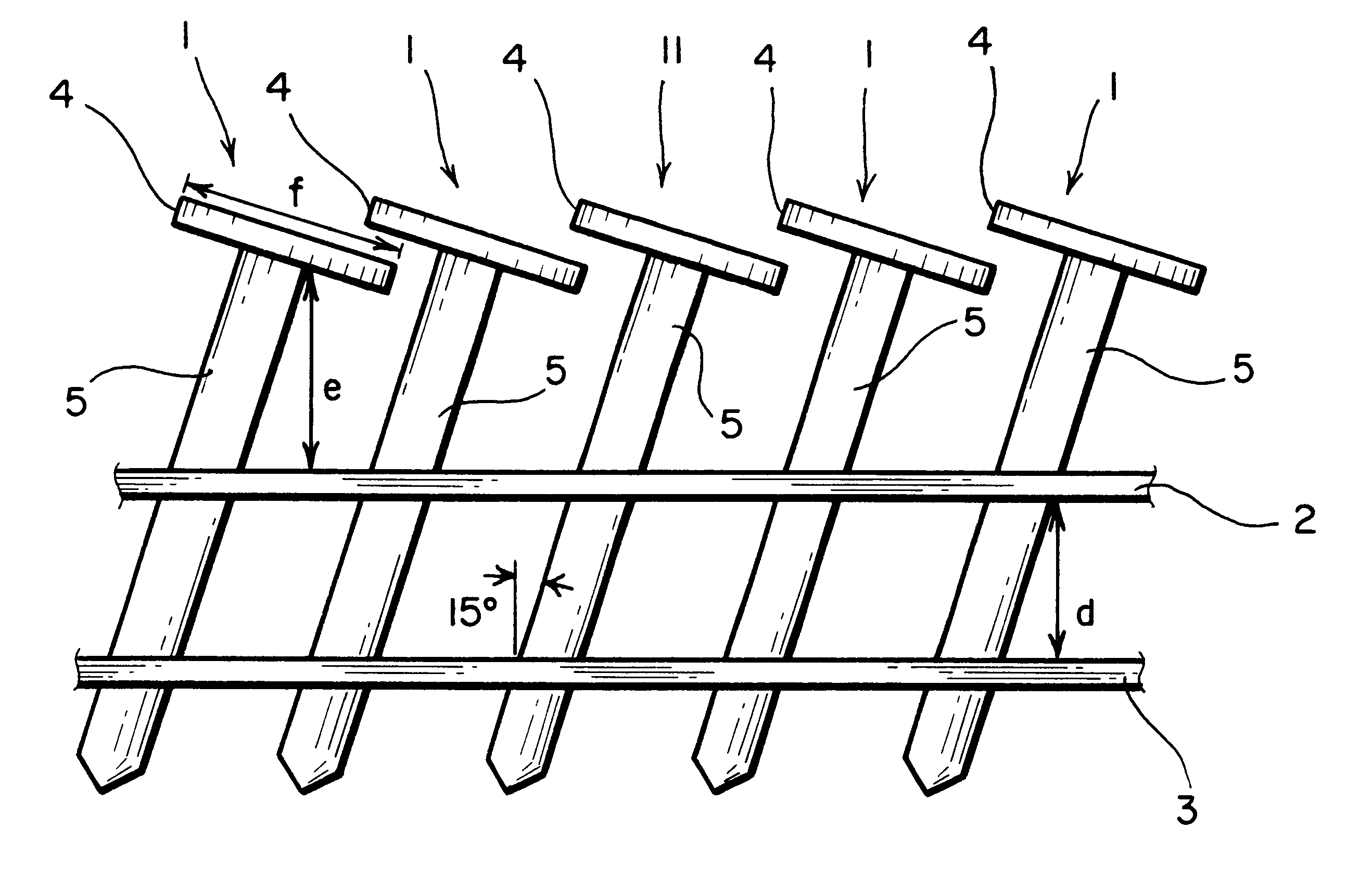
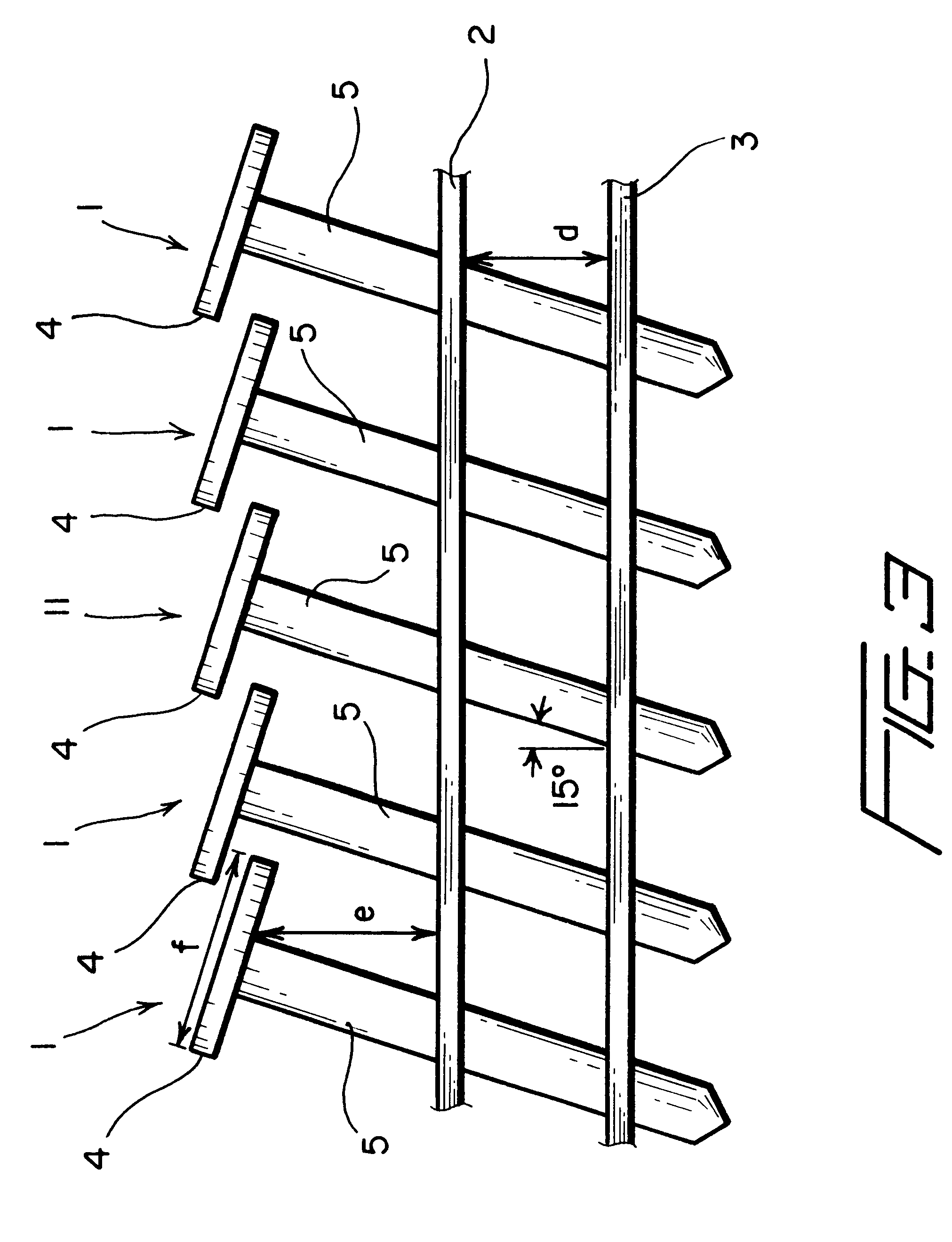
With respective tensile strength of the wire, the problem is solved for nails 14 to 25 mm long and a shaft diameter of 2 to 3 mm, preferably 2.5 mm in that the wires are pitched at 6.5 to 7.5 mm, preferably 7 mm, to each other. At the predetermined nail length and pitch claimed by this invention, only a minimal deviation of the nail pitch from the desired position is possible, which prevents jamming of the nailing device. At the same time, the pitch between nails is short enough for the impact element of the nailing device to impact on both connecting points of wire to nail, thus ensuring a reliable separation of the nail from the wires.
According to a preferred embodiment, nails with heads are preferable. The wire nearer the head is 9 to 11 mm, preferably 10 mm, distant from head to connecting point on the shaft. This distance of the wire nearer the head to the head ensures a trouble free separation of the nail from the wires. The distance of the wire nearer the head is generally equal to the diameter of the head. In an exemplary embodiment, the nail strap contains 70 to 85 nails, preferably 80 nails, which avoids a too frequent changing of the nailing device, while ensuring a usable size and weight of the nail magazine. The size of the coil strap is limited by the weight of the nail strap and by the size of the magazine.
As is known, nails are preferably inclined by 15 degrees to the vertical with the wires being in horizontal position. As described previously, quenched and tempered connecting wires are preferred, which keep the nails in a somewhat flexible position, thus avoiding malfunction. This feature is however not sufficient in all cases. Furthermore it may be necessary to use ordinary coil strapped nails without quenched and tempered wires.

Problems solved by technology

The size of the coil strap is limited by the weight of the nail strap and by the size of the magazine.

Method used


Image

  • Coil strap with nails for use in a nail hammer
  • Coil strap with nails for use in a nail hammer
  • Coil strap with nails for use in a nail hammer

Examples


Embodiment Construction

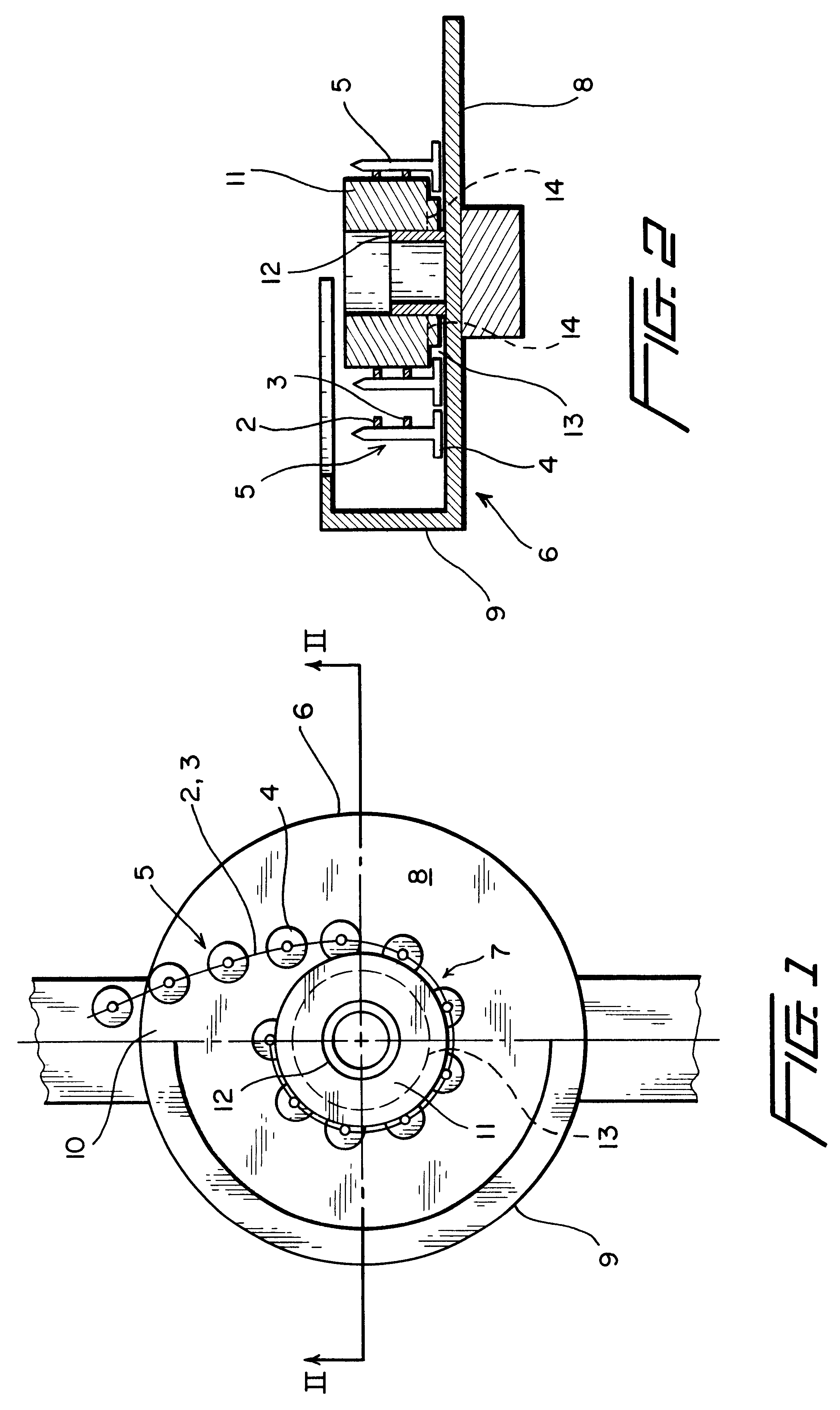
FIG. 1 shows a top view of a magazine of the nailing device as is applicable to EP 0 321 440. Other relevant parts of the nailing device, as well as the magazine lid, have been deleted to give a clearer picture. In magazine (6) lies the nail strap coil. It consists of a series of nails which are connected by means of two wires (2,3) arranged one above the other to form a strap.

The illustration shows the coil in its final stage where most of the nails have been used up. The magazine floor is identified as 8. The magazine wall (9) extends over one half of the magazine. The magazine can be closed with a lid, whereby the nail strap exits via opening (10) towards the hammerhead, which is not shown here. According to the invention under consideration a wrapping sleeve (11) is required, which together with coil (7) is fitted to stub (12) of the magazine and allowed to rotate.

One design of the wrapping sleeve features an annular groove (13) on the side facing the magazines floor (8), which ...


PUM


Abstract

Coil strapped nails and a nailing device using coil strapped nails are provided. The coil may be provided with steel nails (1) having a length of 14 to 25 mm and a shaft diameter of 2 to 3 mm. The nails are held by wires (2,3) 6.5 to 7.5 mm apart, wherein the wires are preferably quenched and tempered. In the center of the coil a wrapping sleeve may be provided having due clearance for the nail heads.

Description

I. BACKGROUND OF THE INVENTION1. Field of the InventionThe present invention relates to coil strapped nails, as well as a nailing device and nail coil for use in a nailing device. More particularly, the invention relates to a coil strap with steel nails, which are integrally connected by means of at least two wires, as well as a nail strapped coil and a nailing device.2. Description of the Related TechnologyNailing devices, which are powered by compressed air, gas, electrical energy or by hand and which use nails stored in a magazine are known in the art. Typically a nailing magazine contains up to 140 parallel-aligned nails, which are connected, e.g. welded, to each other by means of a wire at the nail shafts. The ductility of the wire permits a wrapping of the nail strap into a coil, in which shape it is used in the respective nailing device. Current designs feature connecting wires made of soft, unalloyed metals, which permit easy coiling and welding of the wire-nail connection. ...

Claims


Application Information

Patent Timeline
Patent Type & Authority Patents(United States)
IPC IPC(8): B25C1/00F16B15/00F16B15/08
CPCF16B15/08B25C1/003
Inventor LEITNER, HELMUT
Owner LEITNER HELMUT
Learn More