Device for connecting a submerged fluid-transporting line

a technology of fluid transportation and device, which is applied in the direction of fluid removal, bulkheads/piles, artificial islands, etc., can solve the problems that the traditional hooking-up principle is particularly difficult to implement in an installation, the installation of the fpso unit or the anchor chain of the unit does not facilitate such hooking-up, etc., and achieves the effect of reliable over time and easy installation

Inactive Publication Date: 2003-05-06
TECHLAM
View PDF25 Cites 34 Cited by
  • Summary
  • Abstract
  • Description
  • Claims
  • Application Information

AI Technical Summary

Benefits of technology

An object of the present invention is to mitigate the above-mentioned drawbacks by proposing a connection system that is particularly easy to install. Another object of the invention is to obtain a system that is reliable over time. Yet another object of the invention is to provide a system that can operate regardless of the type of transport line used.

Problems solved by technology

Unfortunately, such a traditional hooking-up principle is particularly difficult to implement in an installation at sea.
In addition, possible interference between the pulling lines and the installations of the FPSO unit or the anchor chains of said unit does not facilitate such hooking-up.

Method used


Image

  • Device for connecting a submerged fluid-transporting line
  • Device for connecting a submerged fluid-transporting line
  • Device for connecting a submerged fluid-transporting line

Examples


first embodiment

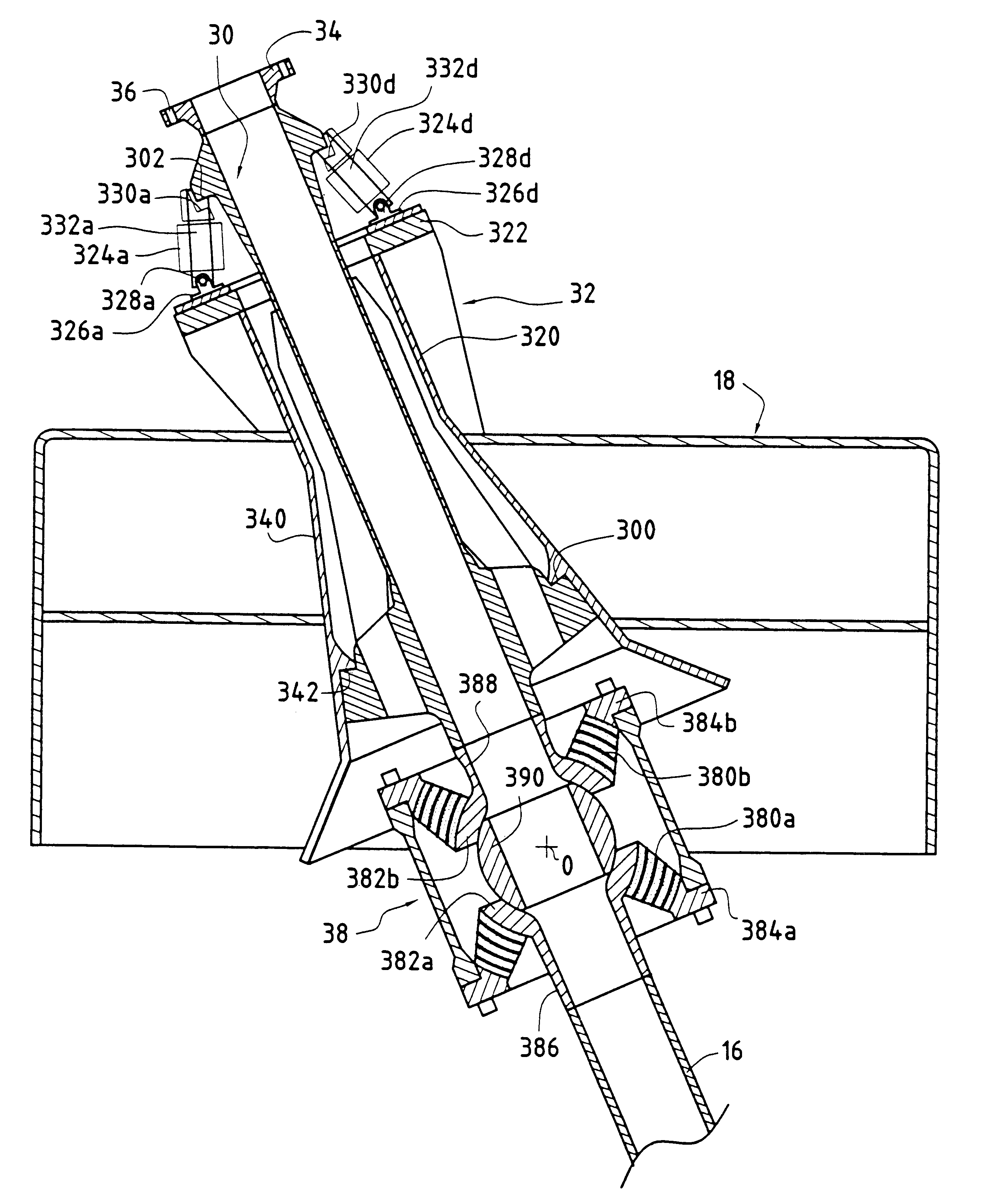
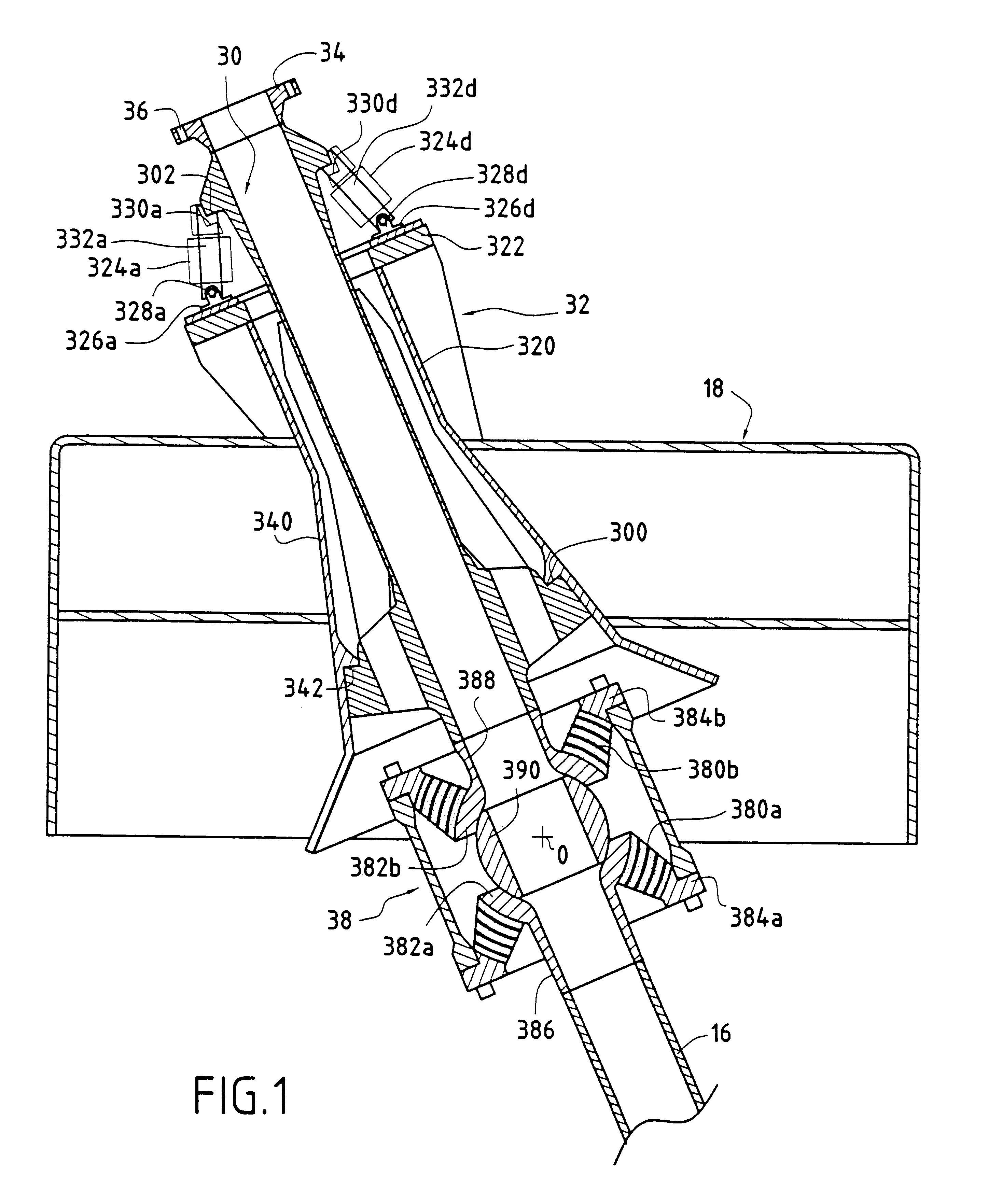
a connector of the invention that serves to connect an offloading line 16 for transporting a petroleum fluid to a mooring buoy 18 is shown in FIG. 1.

This connector includes a first tubular connection element (the male portion 30) serving to be connected to the transport line 16E and a second tubular connection element (the corresponding female portion or "i-tube" 32) that is concentric with the first portion and that is carried by a body portion of the buoy or "buoyancy tank" 18.

A first end of the male tubular portion is fixed, e.g. by welding, to a flange collar 34 whose flange is provided with through orifices 36 for receiving fixing elements for fixing to a pulling line head (not shown). An opposite second end of the male tubular portion is fixed, e.g. by welding, to a first end of hinge means having a spherical laminated abutment 38 whose second end is fixed, e.g. by welding, to the transport line 16 for transporting the fluid under extraction.

In the example shown, the hinge mea...

second embodiment

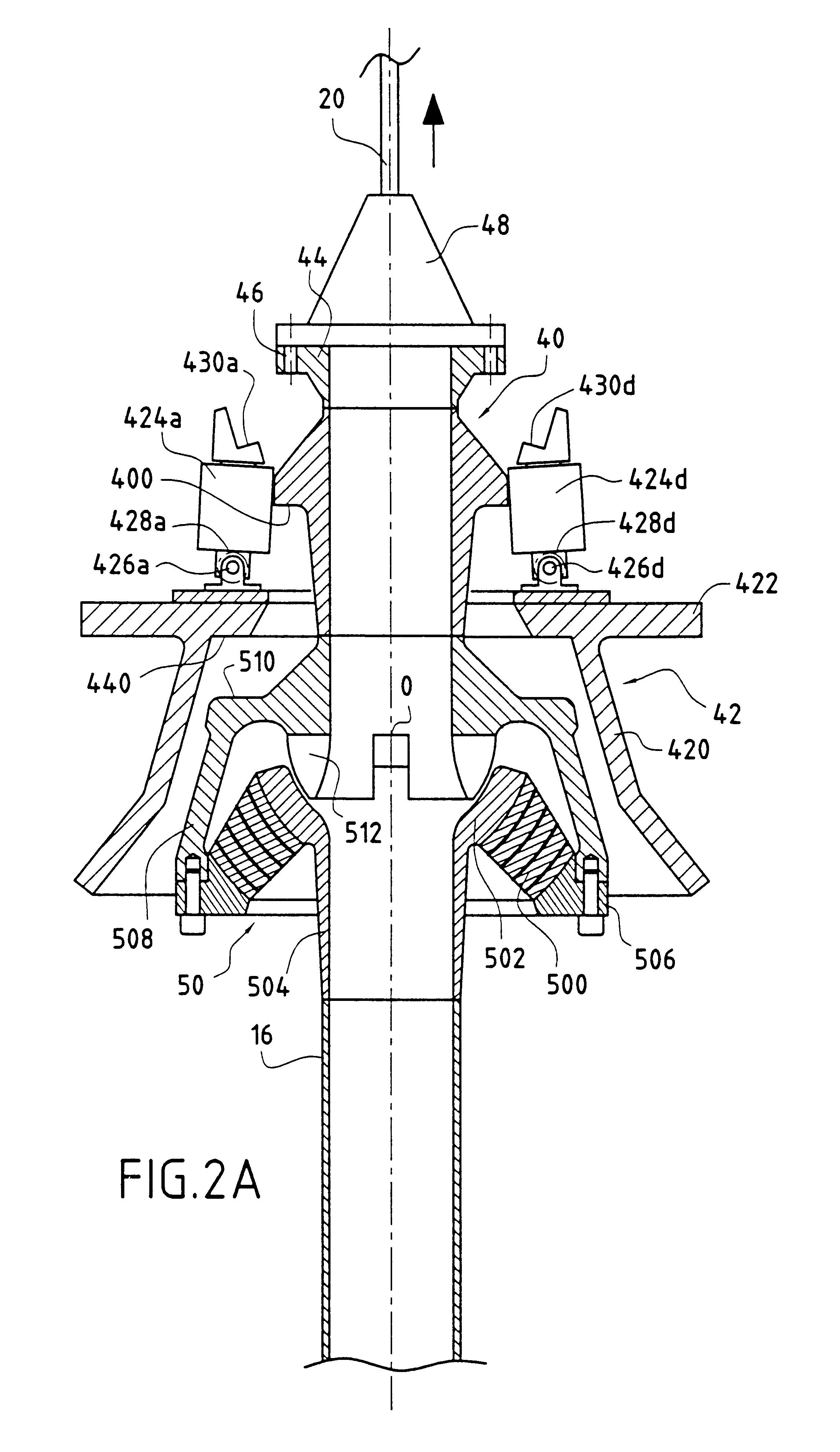
a connector of the invention serving to connect a transport line 16 for transporting a petroleum fluid to a floating support 10 of the FPSO unit type is shown in FIGS. 2a to 2c.

As above, this connector comprises a first tubular connection element (the male portion 40) serving to be connected to the transport line 16, and a second tubular connection element (the corresponding female portion 42) carried by a structural fixed portion of the FPSO unit 10.

A first end of the male tubular portion is fixed, e.g. by welding, to a flange collar 44 whose flange is provided with through orifices 46 for receiving fixing elements for fixing to a head 48 of a single pulling line 20. An opposite second end of the male tubular portion is fixed, e.g. by welding, to a first end of hinge means having a spherical laminated abutment 50 whose second end is secured, e.g. by welding, to the transport line 16.

The hinge means are constituted by a conventional flexible joint assembly incorporating a laminated ...


PUM


Abstract

A connection device for connecting a submerged tubular structure to a floating support structure. The connection device includes first and second tubular connection elements that connect the submerged tubular structure to the floating support structure. The first tubular connection element cooperates with the second tubular connection element to form a first axial abutment in a pulling direction in which the submerged tubular structure is pulled, and a second axial abutment in a direction opposite from the pulling direction. The device further includes a locking and tensioning device that includes at least one actuator secured to the floating support structure and is mounted to pivot on the second tubular connection element about a hinge axis and against the effect of a return spring surrounding the pin so as to enable the first tubular connection element to snap-fasten onto the second tubular connection element.

Description

The present invention relates to the offshore petroleum industry, and it relates more particularly to systems for connecting submerged fluid-transporting lines (all types of "risers") to floating supports (of the following types: floating production, storage and offloading (FPSO) unit; tension leg platform (TLP), submersible pipe-alignment rig (SPAR), buoy, etc.).PRIOR ARTFIG. 7 is a very diagrammatic view of a portion of an offshore petroleum installation. A floating production, storage and offloading (FPSO) unit, referenced 10, is in general disposed immediately above the oil or gas field to be tapped. Tubular structures 12 or "risers" connect the various well heads 14 of the field to the floating support. Rigid offloading lines lead away from this floating unit (e.g. the transport line 16) for offloading the petroleum fluid to tanker ships (not shown) for transporting it. For safety reasons, these tankers are relatively far away from the floating unit 10 and the coupling between ...

Claims


Application Information

Patent Timeline
Patent Type & Authority Patents(United States)
IPC IPC(8): E21B19/00E21B43/01E21B43/00
CPCE21B43/0107E21B19/004F16L27/103
Inventor MOOG, OLIVIERTHUET, SYLVAIN
Owner TECHLAM
Why Eureka
Try Eureka