Motorized antenna pointing device

Inactive Publication Date: 2003-05-06
BELLSOUTH INTPROP COR
View PDF40 Cites 43 Cited by
  • Summary
  • Abstract
  • Description
  • Claims
  • Application Information

AI Technical Summary

Benefits of technology

Over the years, many improvements to televisions and devices and methods for transmitting and receiving television signals have been made. In the early days of television, signals were transmitted and received through the use of antennas. Signal strength and quality, however, were often dependent upon the geography of the land between the transmitting antenna and the receiving antenna. Although such transmission methods are still in use today, the use of satellites to transmit television signals is becoming more prevalent. Because satellite transmitted signals are not hampered by hills, trees, mountains, etc., such signals typically offer the viewer more viewing options and improved picture quality. Thus, many companies have found offering satellite television services to be very profitable and, therefore, it is anticipated that more and more satellites will be placed in orbit in the years to come. As additional satellites are added, more precise antenna / satellite alignment methods and apparatuses will be required.

Problems solved by technology

Those devices are not designed such that they can be used to orient an antenna and then removed therefrom in order that they can be used to orient another antenna.

Method used


Image

  • Motorized antenna pointing device
  • Motorized antenna pointing device
  • Motorized antenna pointing device

Examples


Embodiment Construction

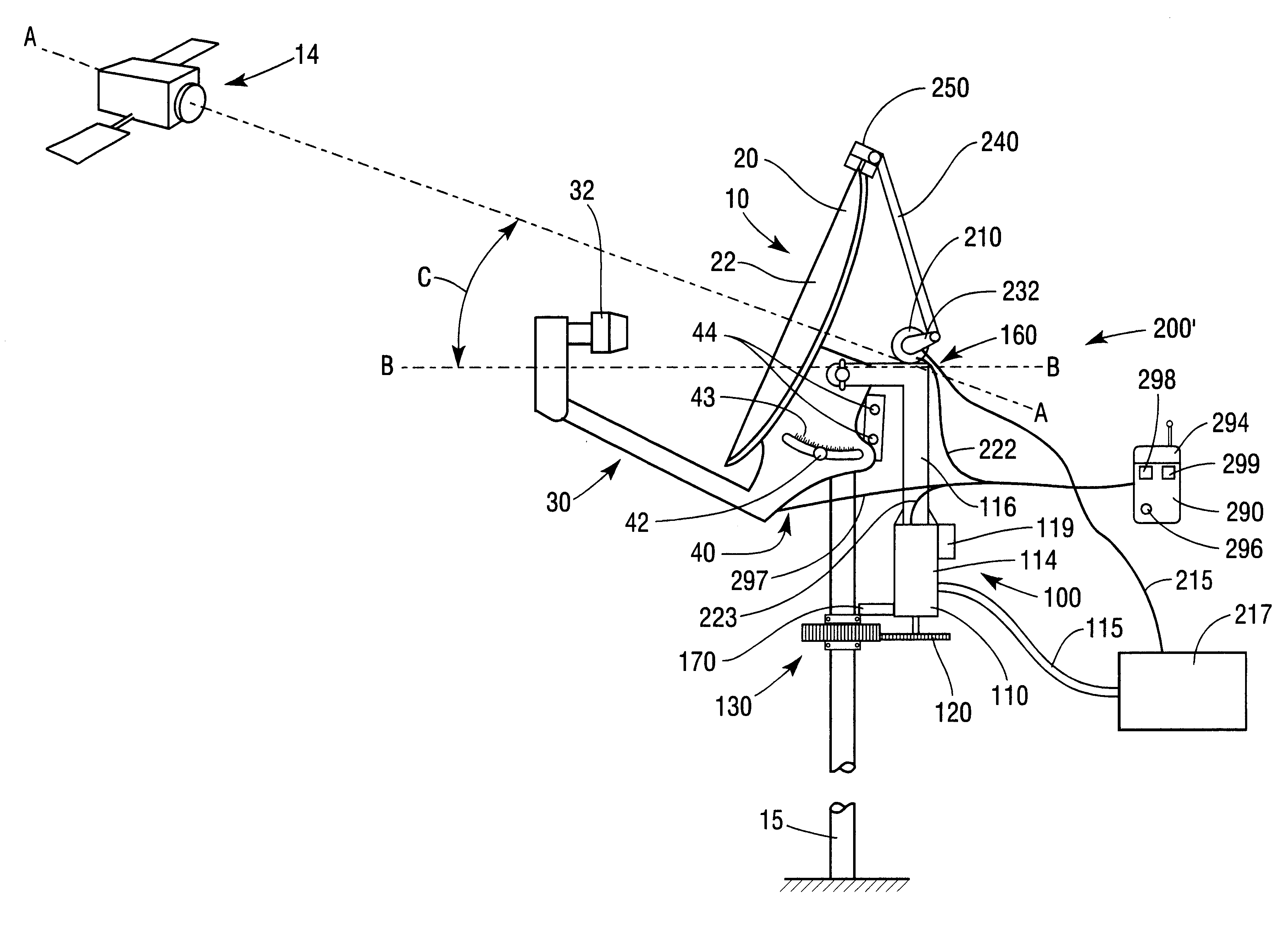
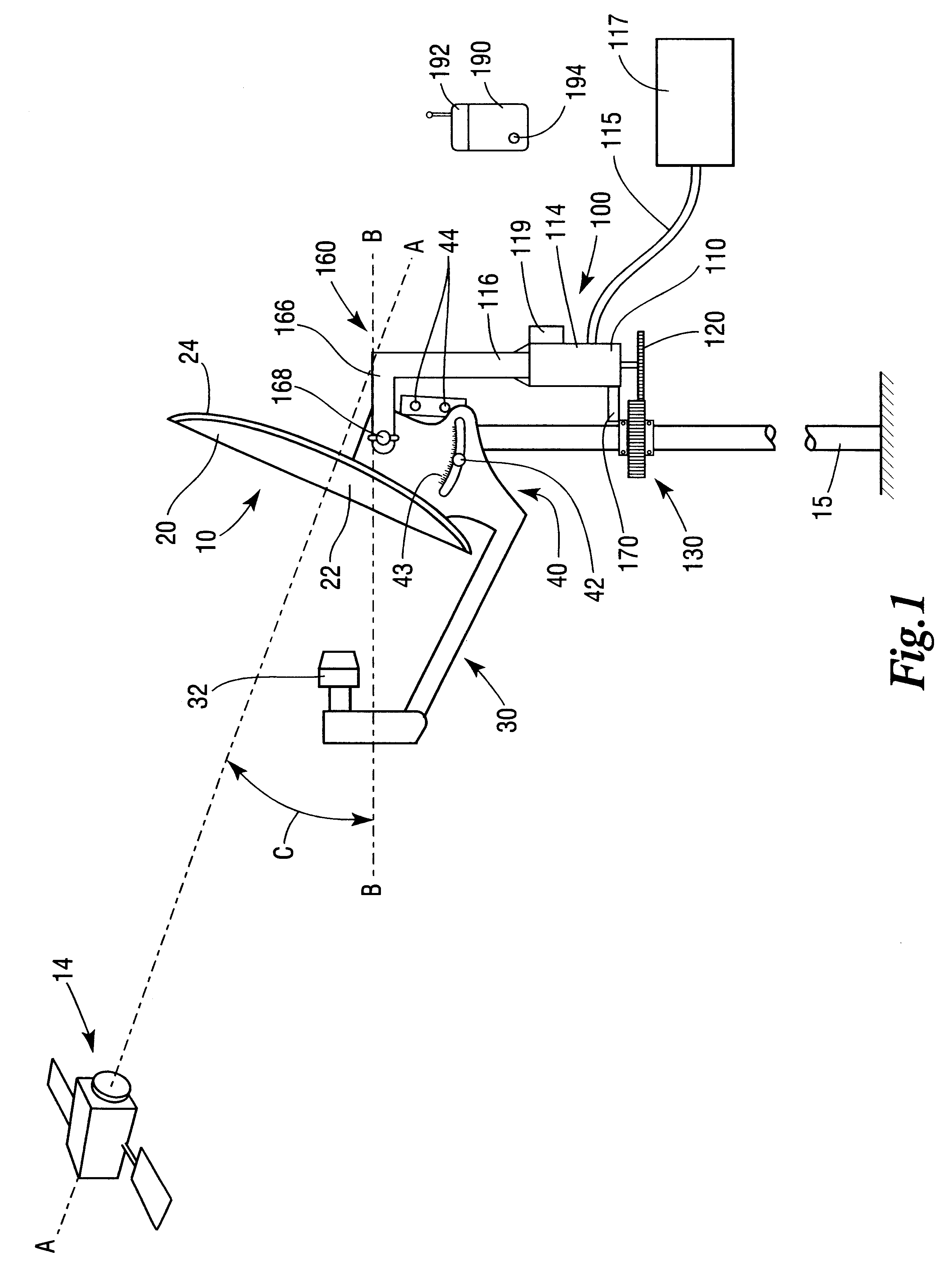
Referring now to the drawings for the purposes of illustrating embodiments of the invention only and not for the purposes of limiting the same, FIG. 1 illustrates a conventional antenna or receiver 10 that is supported by a vertically extending antenna mast 15. The mast 15 is mounted in the earth or attached to a structure (building, tree, etc.) such that it is plumb. Those of ordinary skill in the art will appreciate that various conventional methods exist for ensuring that the mast 15 is "plumb". For example, a convention level or plumb bob could be used.

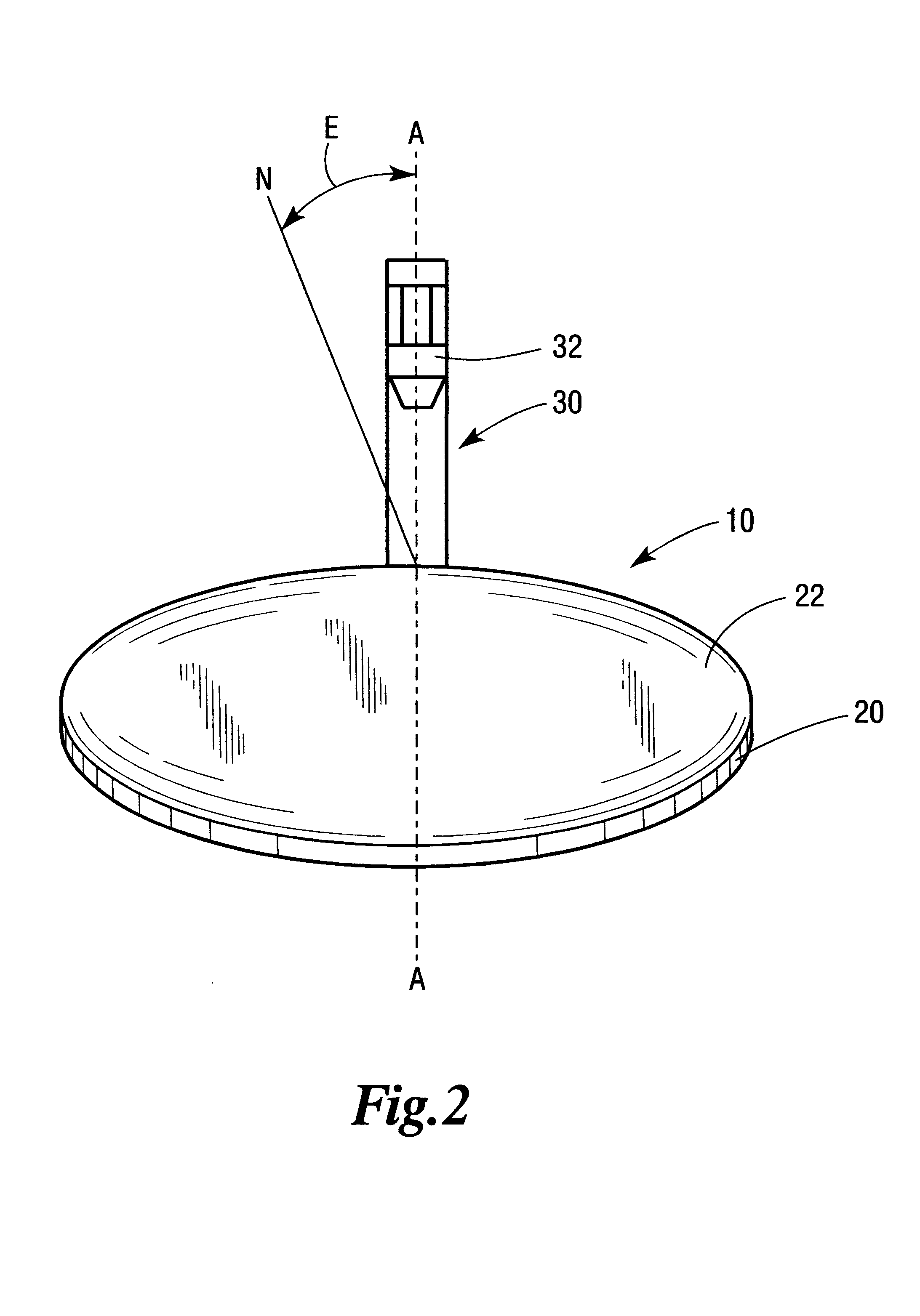
In this embodiment, the antenna 10 includes parabolic dish 20 and an arm assembly 30 that supports a LNBF 32 for collecting focused signals from the dish 20. Such LNBFs are known in the art and, therefore, the manufacture and operation of LNBF 32 will not be discussed herein. The dish 20 has a front surface 22 and a rear surface 24. A conventional mounting bracket assembly 40 is attached to the rear surface 24 of the dish and serv...


PUM


Abstract

Portable alignment devices for orienting a receiver such as an antenna in a desired elevation and methods for orienting a receiver in a desired elevation orientation. In other embodiments, portable alignment devices for orienting a receiver in a desired elevation orientation and in a desired azimuth orientation and methods for orienting an antenna in desired elevation and azimuth orientations.

Description

FEDERALLY SPONSORED RESEARCHNot applicable.1. Field of the InventionThe subject invention relates to alignment devices and, more particularly, to devices for aligning an antenna with a satellite.2. Description of the Invention BackgroundThe advent of the television can be traced as far back to the end of the nineteenth century and beginning of the twentieth century. However, it wasn't until 1923 and 1924, when Vladimir Kosma Zworkykin invented the iconoscope, a device that permitted pictures to be electronically broken down into hundreds of thousands of components for transmission, and the kinescope, a television signal receiver, did the concept of television become a reality. Zworkykin continued to improve those early inventions and television was reportedly first showcased to the world at the 1939 World's Fair in New York, where regular broadcasting began.Over the years, many improvements to televisions and devices and methods for transmitting and receiving television signals have...

Claims


Application Information

Patent Timeline
Patent Type & Authority Patents(United States)
IPC IPC(8): H01Q1/12H01Q3/02
CPCH01Q3/02H01Q1/125
Inventor WATSON, P. THOMAS
Owner BELLSOUTH INTPROP COR
Why Eureka
Try Eureka