
Method for transferring image information, method for updating image information, transferring apparatus and updating apparatus

Inactive Publication Date: 2003-05-06
AU OPTRONICS CORP
View PDF14 Cites 23 Cited by
  • Summary
  • Abstract
  • Description
  • Claims
  • Application Information

AI Technical Summary

Benefits of technology

In addition, another object of the present invention is to enable more natural display of image information transferred via a transmission line with limited band width by using a simple mechanism.
In addition, still another object of the present invention is to reduce power consumption and unnecessary radiation by lowering transmission rate of image information.
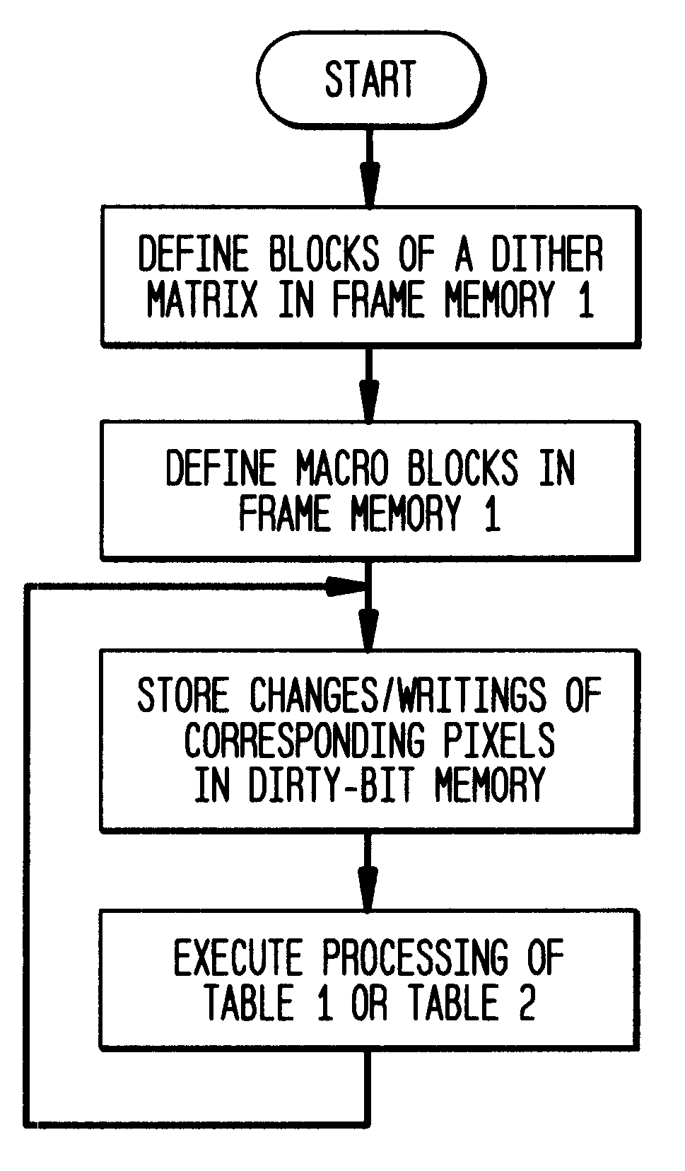
The present invention is to be handled as follows. If first image information which is stored in a first apparatus and comprises a plurality of pixels is transferred to a second apparatus in order to update second image information stored in the second apparatus, following steps are performed: defining a plurality of blocks in the first image information, wherein each block has a size of a predetermined dither matrix; and transferring each pixel information in each block to the second apparatus in order of a value of a corresponding element of the dither matrix. By transferring in order of a value of a corresponding element in the dither matrix, it becomes possible to transfer image information of high resolution even if the transmission line has low band width and to update and display image information in a natural form in the second apparatus. Moreover, it is also possible to put each pixel an order of transfer before transferring and to transfer them in that order thereafter.
The second aspect of the present invention is as follows. That is, if image information which is stored in a first apparatus and comprises a plurality of pixels is transferred to a second apparatus, wherein the pixels are divided into blocks, and each block has a size of a predetermined dither matrix, following steps are performed: determining, in order of a value of a corresponding element in the dither matrix, whether each pixel in each block of the image information should be transferred to the second apparatus; and transferring information of the pixels which are determined to be transferred in the order to the second apparatus. In this way, it is possible to avoid information transfer of unnecessary pixels, whereby the amount of transferring data is reduced. It may further include a step of changing a bit which corresponds to image information of a pixel changed by the first apparatus and represents whether the pixel is changed or not (written or not) to a state of changed (written).
Furthermore, it is also possible to include a step of performing, in said first apparatus, a processing for moving a portion of the image information to another part in the image information; and a step of transferring to the second apparatus a command for performing the same processing for moving. In this way, it is possible to reduce the amount of data to be transferred, which is less than changed pixels. In this case, a following step may be further included: a step of moving the content of bits which correspond to the moved portion of the image information, each of which represents whether a change (writing) of a pixel is made, to a position for another portion of the image information in bits, each of which represents whether a change (writing) of a pixel is made. It is also possible to include a step of determining whether a pixel to be transferred is included in a group comprising one or a plurality of the blocks; and if it is determined that no pixel is to be transferred, skipping the step of determining whether each pixel in each block of the image information and the subsequent steps for a predetermined pixel in the group. In this way, the amount of transferring data may be further reduced.
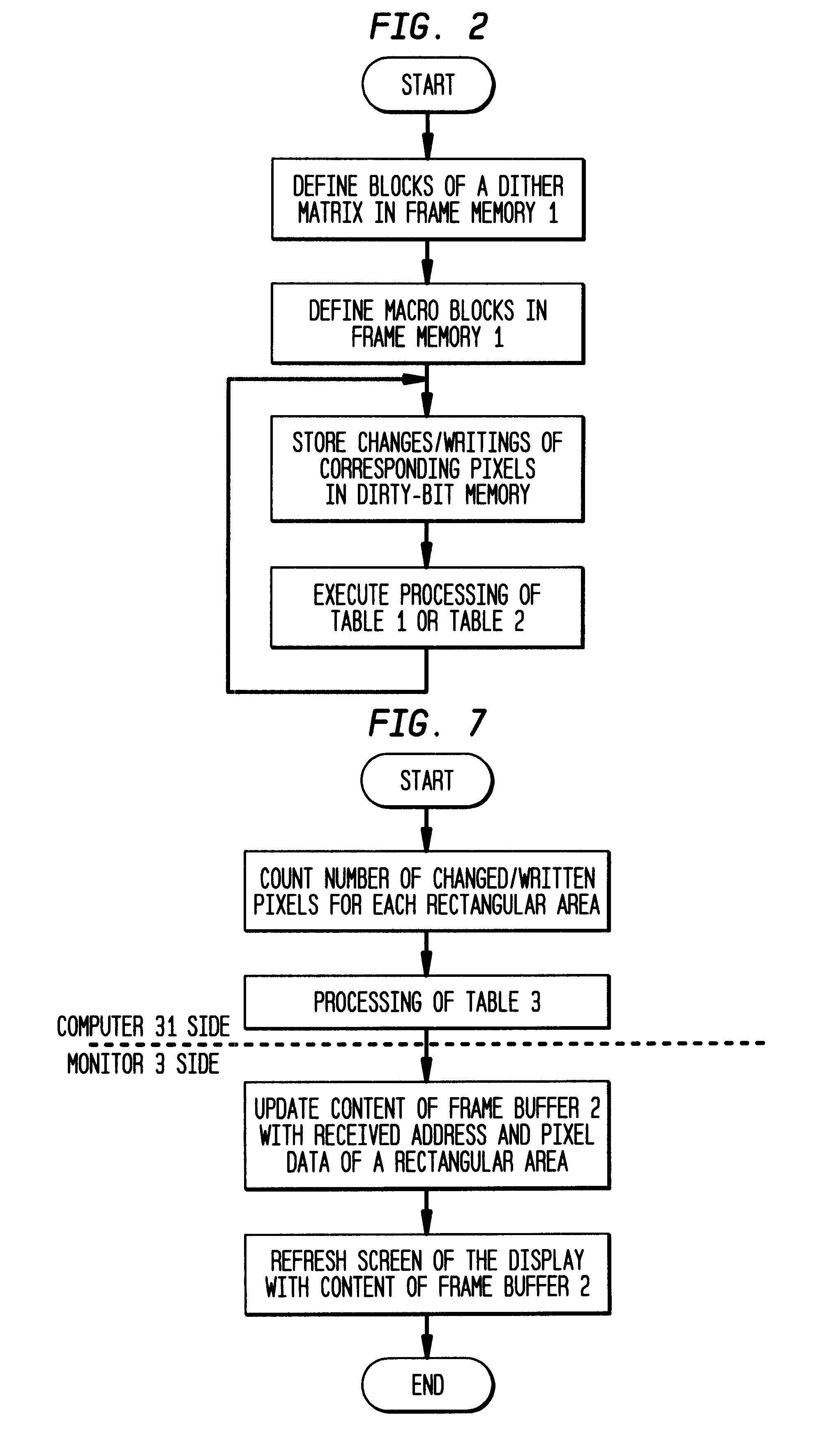
If the count is determined not to have exceeded the predetermined threshold, it is possible to increment the count. This is for the purpose of preventing the situation where the count value does not exceed a predetermined threshold no matter how often the count value of a certain block is checked and the screen is never updated. That is, it must be transferred by the block at least once in several times.

Problems solved by technology

This patent does not disclose any detailed method for transferring the data from the VRAM to the RAM in the X driver of the LCD module.
However, the transmitting and receiving sides must execute more complicated processing.
Theoretically it should be based on changes rather than writings, but there is a drawback that detecting changes requires great load.

Method used


Image

  • Method for transferring image information, method for updating image information, transferring apparatus and updating apparatus
  • Method for transferring image information, method for updating image information, transferring apparatus and updating apparatus
  • Method for transferring image information, method for updating image information, transferring apparatus and updating apparatus

Examples


Embodiment Construction

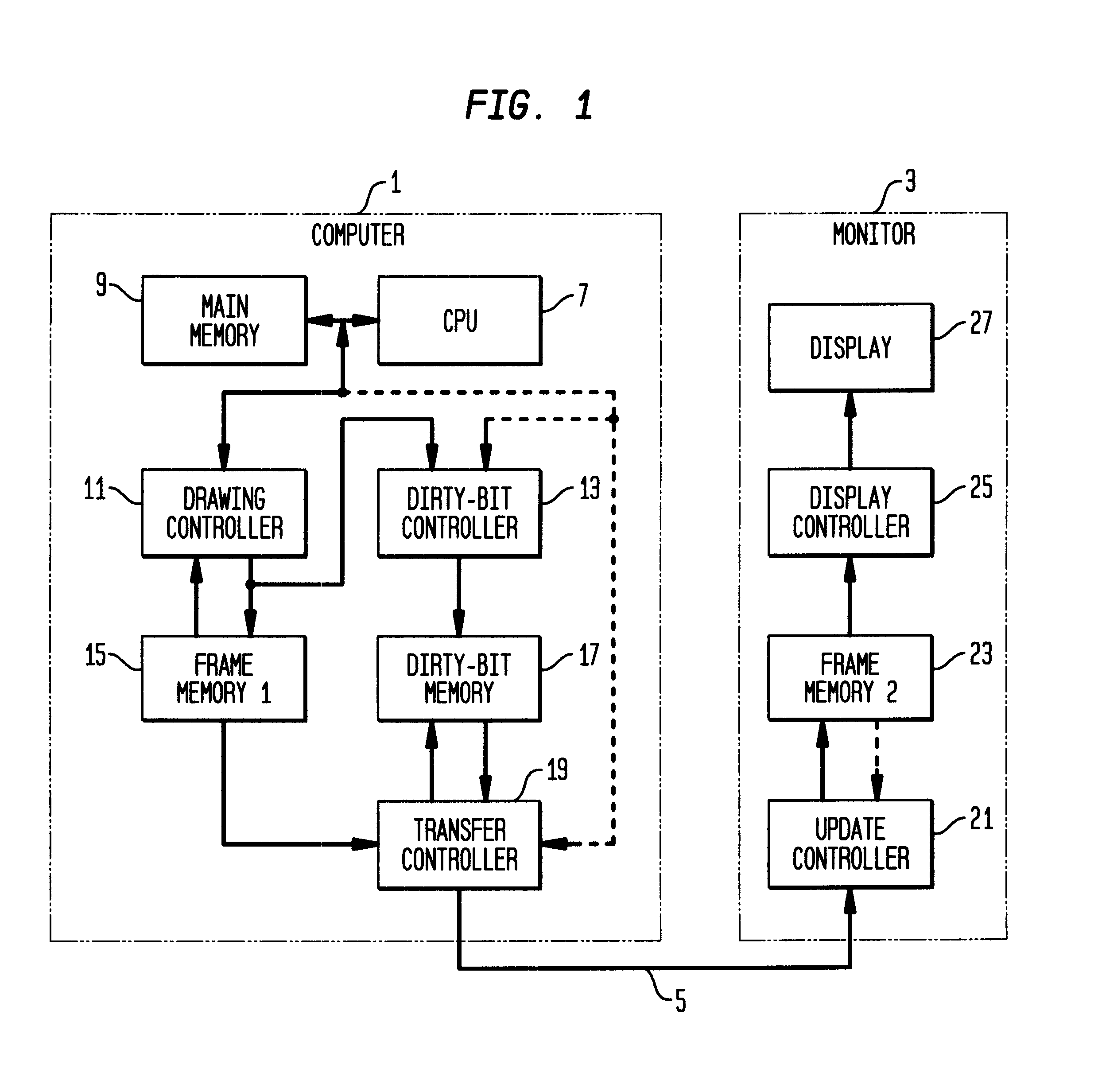
FIG. 1 shows a configuration according to the present invention. A computer 1 is connected to a monitor 3 via a transmission line 5. The computer 1 comprises a CPU 7, a main memory 9, a drawing controller 11, a frame memory 1 (15), a dirty-bit controller 13, a dirty-bit memory 17 and a transfer controller 19. On the other hand, the monitor 3 comprises an update controller 21, a frame memory 2 (23), a display controller 25 and a display 27. For instance, suppose the display 27 is a display device of high resolution such as 1600.times.1200 or 2048.times.1536 pixels, and the transmission line 5 has only band width which does not allow data of all pixels to be transferred in vertical scanning period (about 60 Hz) of such display 27. Technically it is possible to provide a transmission line 5 of high speed, but it will raise transmission cost significantly. Therefore, the present invention reduces this transmission cost and enables transmission of high resolution images. The dotted line ...


PUM


Abstract

The present invention enables image information of high resolution to be transferred via a transmission line with limited band width using a simple configuration. In transferring image information between a main body of a computer and a display, a dither matrix is used to update images stored in the display. That is, a plurality of blocks whose size is of a predetermined dither matrix are defined in an image, and information of each pixel in each block is transferred to the display in order of a value of a corresponding element in the dither matrix. Transfer of unchanged pixel data can be omitted. In addition, in transferring image information between the main body of the computer and the display, image information stored in the computer is divided into a plurality of blocks, for each of which the number of changed pixels or the number of writings to pixels in the block is calculated so that image information in blocks which exceed a predetermined number is transferred to the display block by block.

Description

1. Technical FieldThe present invention relates to a method for transferring image information.2. Prior ArtFollowing techniques have been employed: to equip both of a main body of a computer and a display device with a storage device storing image information, to communicate between them if image information stored in the storage device in the main body of the computer is updated by the main body of the computer and to limit data transferred from the main body of the computer to an updated portion, and to refresh displayed content on the display device with image information stored in the storage device in the display device. For instance, U.S. Pat. No. 5,726,677 discloses that VRAM of the main body of the computer is connected to RAM in an X driver of an LCD module via a special bus and if data of the VRAM is updated, the updated portion is transferred via the special bus. This patent does not disclose any detailed method for transferring the data from the VRAM to the RAM in the X ...

Claims


Application Information

Patent Timeline
IPC IPC(8): G09G3/20G09G3/36G06F3/153G06F13/00G06T1/60G09G5/00H04N1/41H04N7/18
CPCG09G5/006G09G3/3629G09G2310/04
Inventor KAWASE, KEIMORIYAMA, TAKAONAKAMURA, FUSASHI
Owner AU OPTRONICS CORP
Learn More