Fractionating apparatus

a technology of fractionating apparatus and spherical filter, which is applied in the direction of feeding/discharge of settling tanks, chemical/physical processes, library member identification, etc., can solve the problems of affecting the efficiency of the fractionating apparatus

Inactive Publication Date: 2003-05-13
MORITEX CORP
View PDF5 Cites 8 Cited by
  • Summary
  • Abstract
  • Description
  • Claims
  • Application Information

AI Technical Summary

Benefits of technology

Since the valve is operated based on the detection signals of each of the photosensors in each of the sample elution systems, when only the solvent is discharged with no elution of the ingredients, it is discharged into a drain as it is and only when the ingredient is eluted, the ingredient can be dropped into the fractionation vessel, so that wasteful collection only for the solvent to the fractionation vessel can be avoided.
In this case, it is not necessary to move the nozzles in the lateral direction but they only have to be moved reciprocally, the structure of the nozzle driving mechanism can be made simple to reduce the worry of failure.

Problems solved by technology

However, since several tens kinds of samples are synthesized simultaneously in the combinatorial chemistry, if fractionation is conducted on every samples, it takes as much as 6 to 7 hours for only fractionating samples even of ten kinds of them if column exchange time or the like is taken into consideration.
However, since elution time is different due to the difference of the ingredients contained in each of the samples, it may sometimes occur that while sample ingredients are eluted from one column, sample ingredients are not yet eluted from other columns.
An extremely large number of ingredients can not sometimes be coped with fractionation vessels only for one row but increase of the number of fractionation vessels in each row makes the size of the fractionating apparatus larger.
As described above, when plurality of sample elution systems are merely provided irrespective of the difference for the timing of dropping ingredients or the amount of dropping to individual fractionation vessels in accordance with samples, eluates are dropped evenly from all of the sample elution systems into fractionation vessels, to result in a problem that the substances can not be fractionated in accordance with the ingredients contained in each of the samples.

Method used


Image

  • Fractionating apparatus
  • Fractionating apparatus
  • Fractionating apparatus

Examples


Embodiment Construction

This invention will be explained by way of preferred embodiments with reference to the drawings.

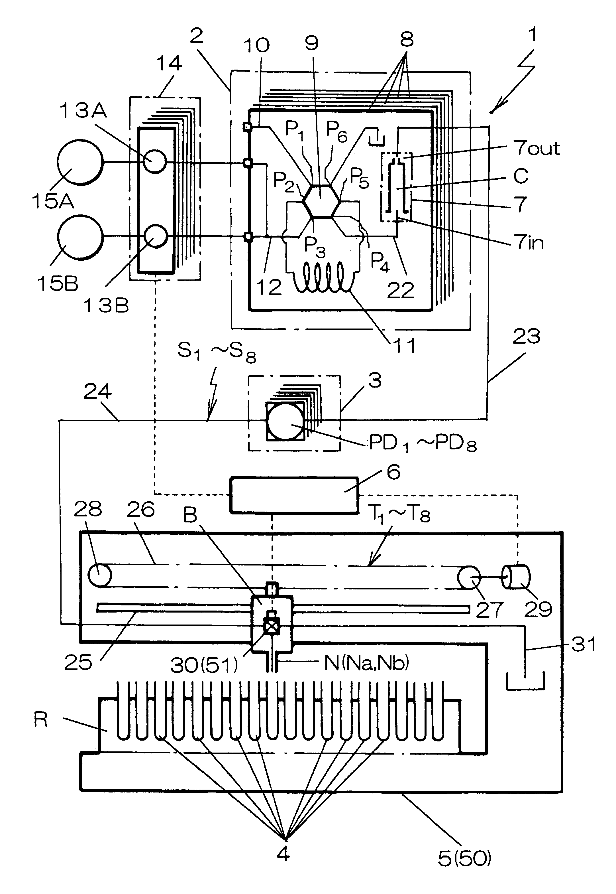
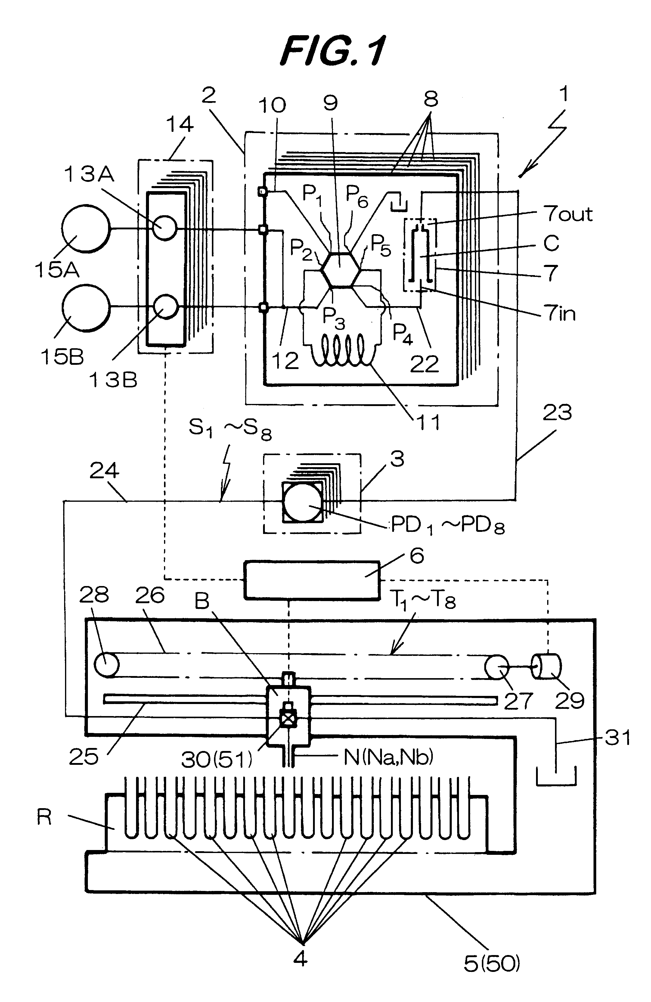
A fractionating apparatus shown in FIG. 1 comprises a column stand 2 for supplying a solvent to columns C, C, in which samples are adsorbed to elute sample ingredients, a detection device 3 for detecting whether the sample ingredient is contained or not in the solvent discharged from each of the columns C, C, --- by UV-ray sensors PD.sub.1 to PD.sub.8, a fraction collector 5 for successively dropping the sample ingredients to test tubes (fractionation vessels) 4, 4, --- in each of rows arranged in a 20.times.8 matrix and a control device 6 for controlling the fraction collector 5 based on the direction signals from the detection device 3.

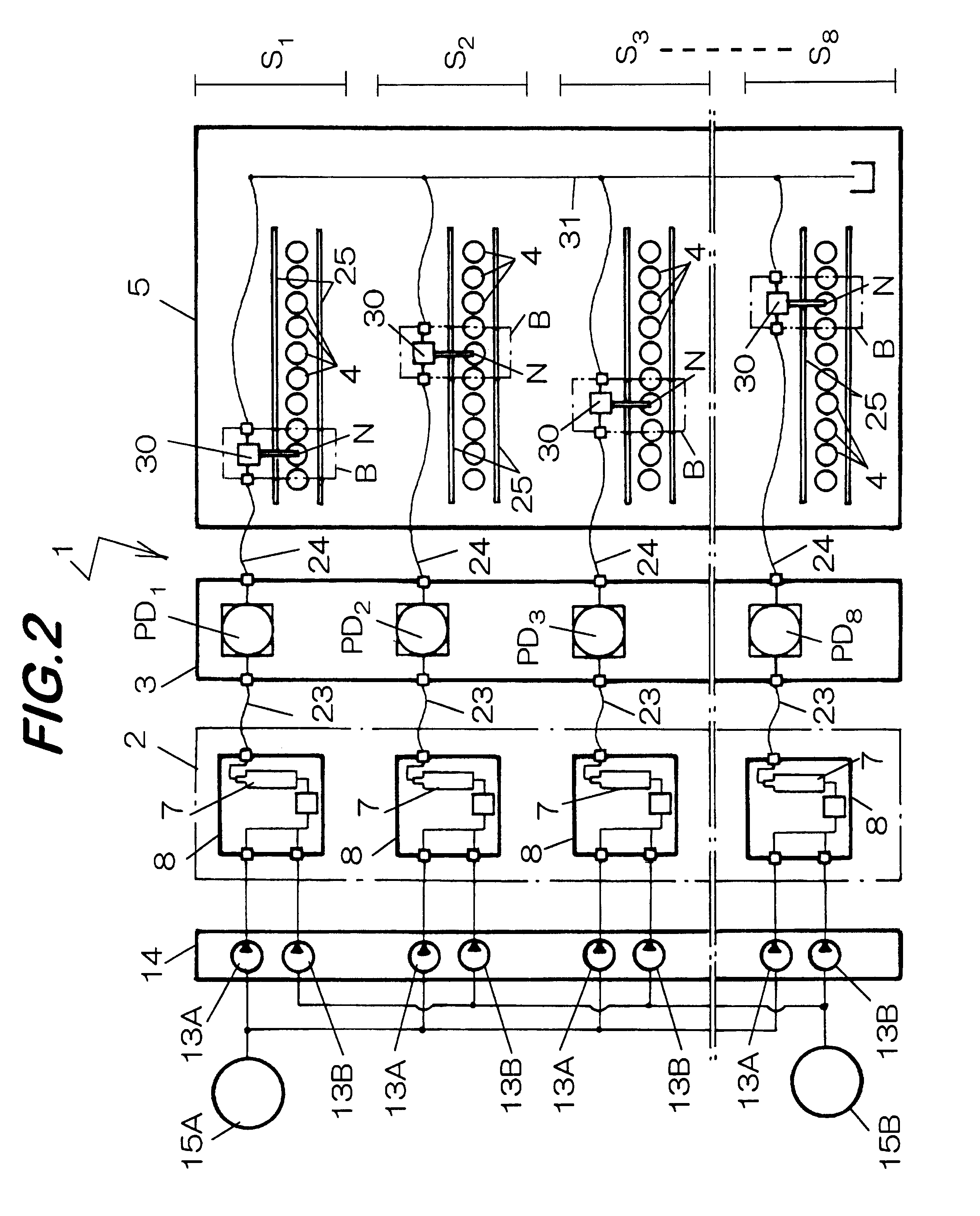
Then, eight sample elution systems S.sub.1 -S.sub.8 are formed to the fractionating apparatus 1 for successively dropping sample ingredients passed from each of the columns C, C, --- through each of the detection devices 3 and then eluted into test tubes ...


PUM

PropertyMeasurementUnit
diameteraaaaaaaaaa
diameteraaaaaaaaaa
diameteraaaaaaaaaa

Abstract

Fractionating apparatus having a plurality of sample elution system (S1-S8) in which a nozzle (N) movable in the direction of the row of fractionation vessels (4, 4, ---) arranged in a matrix is disposes to each of the sample elution system (S1-S8) and kept standing-by just above an empty fractionation vessel (4), a valve (30) is operated when elution of sample ingredients is detected by photosensor (PD1-PD8) to drop the sample ingredients to the fractionation vessel (4, 4, ---) and the nozzle is moved after dropping the sample ingredient by a required amount, and in which the nozzle (N) and the valve (30) can be operated individually on every sample elution systems at different timings respectively such that the eluate can be dropped at different timing on every sample elution systems.

Description

1. Field of the InventionThe present invention concerns a fractionating apparatus for eluting samples from a plurality of columns simultaneously and dropping ingredients thereof successively each by a required amount to fractionation vessels in each of rows arranged in a matrix.2. Statement of the Related ArtWhen a novel compound is prepared by combining several substances, a combinatorial chemistry has been adopted recently. In this method, several kinds of materials provided previously are mixed at different mixing ratios on every vial tubes to cause chemical reactions and synthesized a number of synthesized samples simultaneously.A fractionating apparatus is used for purifying the thus synthesized samples and analyzing ingredients contained therein and fractionating only the optional effective ingredients.The fractionating apparatus is adapted to fractionate the ingredients of a sample by injecting a sample to a column filled with an adsorbent such as silica, supplying a solvent ...

Claims


Application Information

Patent Timeline
Patent Type & Authority Patents(United States)
IPC IPC(8): B01D15/10B01D15/24G01N30/00G01N30/82G01N30/42G01N37/00B01D15/08B01J4/00C07B63/00C40B20/02C40B60/00C40B60/10G01N30/46G01N30/80
CPCB01D15/247G01N30/82G01N30/42
Inventor MYOGADANI, TORU
Owner MORITEX CORP
Why Eureka
Try Eureka