Measurement method and system for a humidity or gas concentration sensor

a humidity or gas concentration sensor and measurement method technology, applied in chemical methods analysis, instruments, material analysis, etc., can solve the problems of large error in output signal, erroneous correction of device, and infrequent self-calibration steps

Inactive Publication Date: 2003-05-20
OYJ VAISALA
View PDF6 Cites 12 Cited by
  • Summary
  • Abstract
  • Description
  • Claims
  • Application Information

AI Technical Summary

Problems solved by technology

However, as the self-calibration step takes a relatively long time and excludes simultaneous measurement operation of the device, the self-calibration step can be carried out only infrequently.
Hence, if the partial pressure of the gas under measurement does not remain constant during the self-calibration step, an erroneous correction is made on the device reading until the next self-calibration is performed.
However, in this case, the measurement noise causes a larger error in the output signal as compared with other techniques if the measurements are taken at only two points.
Furthermore, the method involves a long update period of output signals even in normal operation, not merely during the self-calibration step, as is the case in U.S. Pat. No. 5,033,284, described above.

Method used


Image

  • Measurement method and system for a humidity or gas concentration sensor
  • Measurement method and system for a humidity or gas concentration sensor
  • Measurement method and system for a humidity or gas concentration sensor

Examples


Embodiment Construction

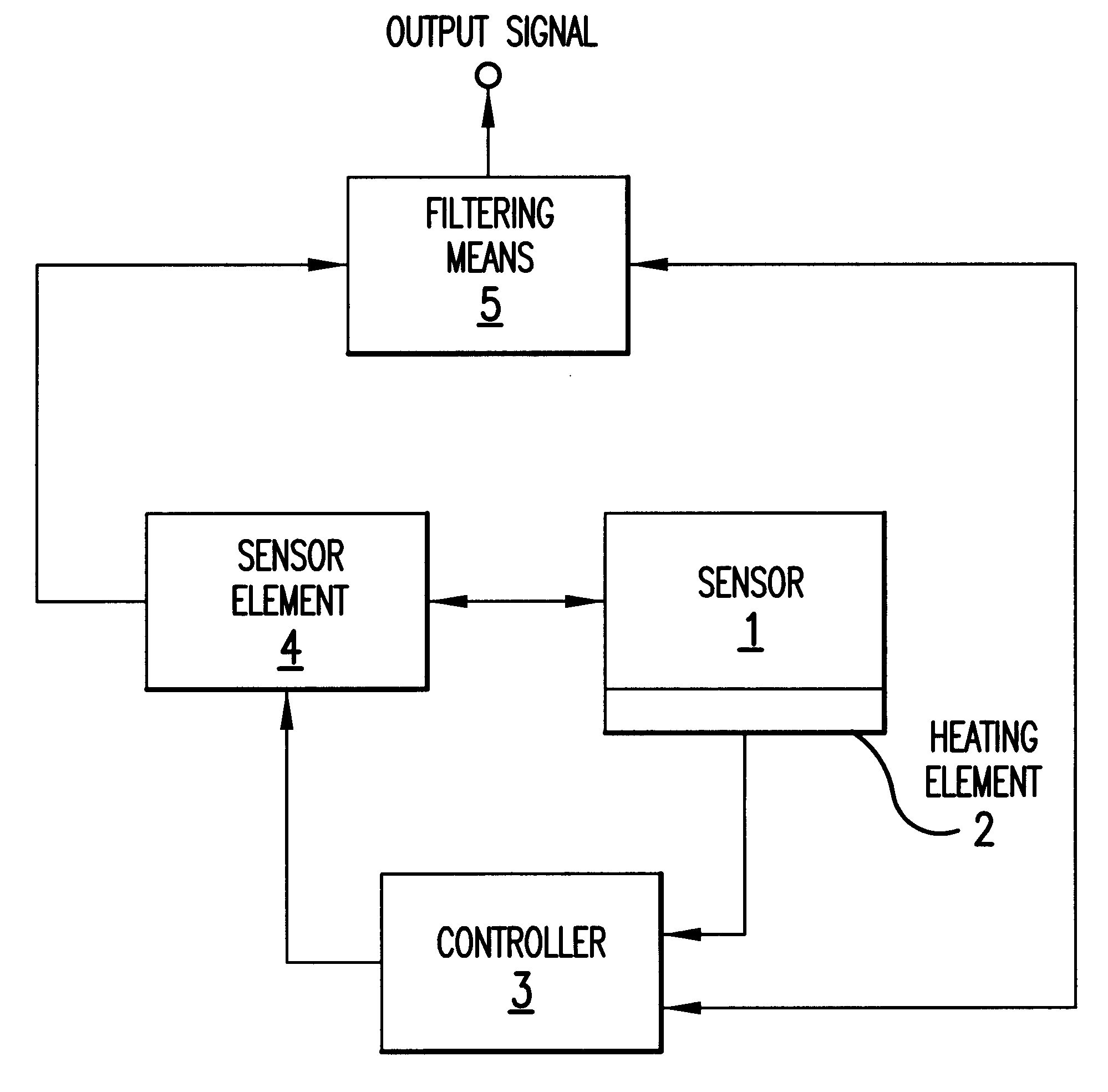
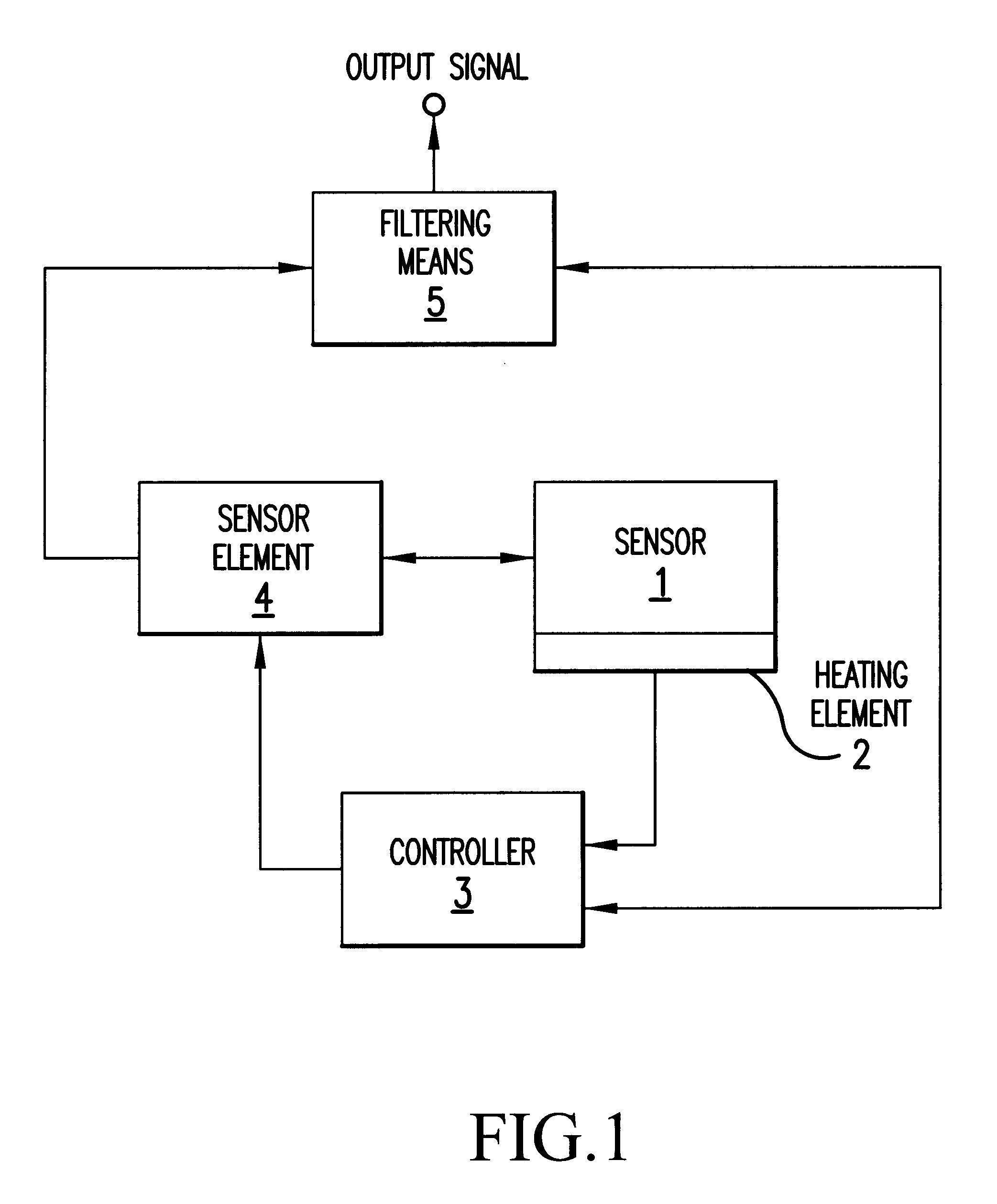
Referring to FIG. 1, the system according to the invention shown therein comprises a gas concentration sensor 1 for measuring the relative humidity of ambient air. The sensor 1 may be, e.g., a capacitive sensor or a resistive gas concentration sensor. A heating and / or cooling element 2 is connected to the sensor 1, and the heating or cooling effect is controlled by a controller 3. The element 2 may be either a conventional resistor or a Peltier element that also is capable of cooling the sensor. A sensor parameter (such as capacitance or resistance) sensitive to the variable being measured by the sensor is detected by a sensor element 4, and the measurement is advantageously synchronized to the control sequence of the heating cycle controller 3. From the measured value of the sensor parameter (capacitance or resistance), an actual measurement signal is generated that is proportional, generally in a linear or at least quasilinear manner, to the absolute or relative concentration of t...


PUM

PropertyMeasurementUnit
RHaaaaaaaaaa
concentrationaaaaaaaaaa
temperatureaaaaaaaaaa

Abstract

A method and system relating to an improvement in measuring accuracy of a gas concentration sensor, the method comprising the steps of measuring a parameter of the sensor, the parameter being a resistance or a capacitance, that is sensitive to the gas or its concentration being measured, and simultaneously changing the temperature of the sensor in a cyclic manner. The parameter of the sensor being measured is measured more than two times or continuously during each heating cycle. The measured parameter value is filtered to obtain a signal component associated with the fundamental frequency of the heating cycle for use at a later step, and the thus filtered signal component is used in the correction and/or calibration of actual output signal of the sensor.

Description

BACKGROUND OF THE INVENTION1. Field of the InventionThe present invention relates to a measurement method and system for use in conjunction with a humidity or gas concentration sensor.2. Description of Background ArtU.S. Pat. No. 5,033,284 discloses a calibration method, wherein a correction factor of the sensor reading can be computed by way of transiently deviating the temperature of the humidity or gas concentration sensor. This method is applicable to an automatic self-test of the measurement device at intermittent intervals. In the method, the partial pressure of the gas under measurement is assumed to stay constant during imposed deviation of the sensor temperature.During normal function of the device, the reading can be updated quite frequently within the confines set by the measurement noise. However, as the self-calibration step takes a relatively long time and excludes simultaneous measurement operation of the device, the self-calibration step can be carried out only infre...

Claims


Application Information

Patent Timeline
Patent Type & Authority Patents(United States)
IPC IPC(8): G01N27/22G01N33/00G01N27/00G01N27/12
CPCG01N27/223G01N27/124
Inventor STORMBOM, LARS
Owner OYJ VAISALA
Why Eureka
Try Eureka