Air gap magnetic mobile robot

a mobile robot and air gap technology, applied in the direction of manufacturing tools, vessel construction, cleaning using liquids, etc., can solve the problems of metal wheels crushing and permanently damaging the paint or protective coating between the wheels and the hull, and the high pressure rotary head cannot be maneuvered to engage the entire surface of the hull, especially the margins

Inactive Publication Date: 2003-05-20
DCP WATERJET HLDG INC
View PDF19 Cites 38 Cited by
  • Summary
  • Abstract
  • Description
  • Claims
  • Application Information

AI Technical Summary

Problems solved by technology

The magnetic attraction between the wheels and the hull is of such magnitude directed through such minimal contact that the metal wheels crush and permanently damage the paint or protective coating between the wheels and the hull.
With the magnetic wheels placed at the four corners of the chassis, the high pressure rotary head could not be maneuvered to engage the entire surface of the hull, particularly the margins.

Method used


Image

  • Air gap magnetic mobile robot
  • Air gap magnetic mobile robot
  • Air gap magnetic mobile robot

Examples


Embodiment Construction

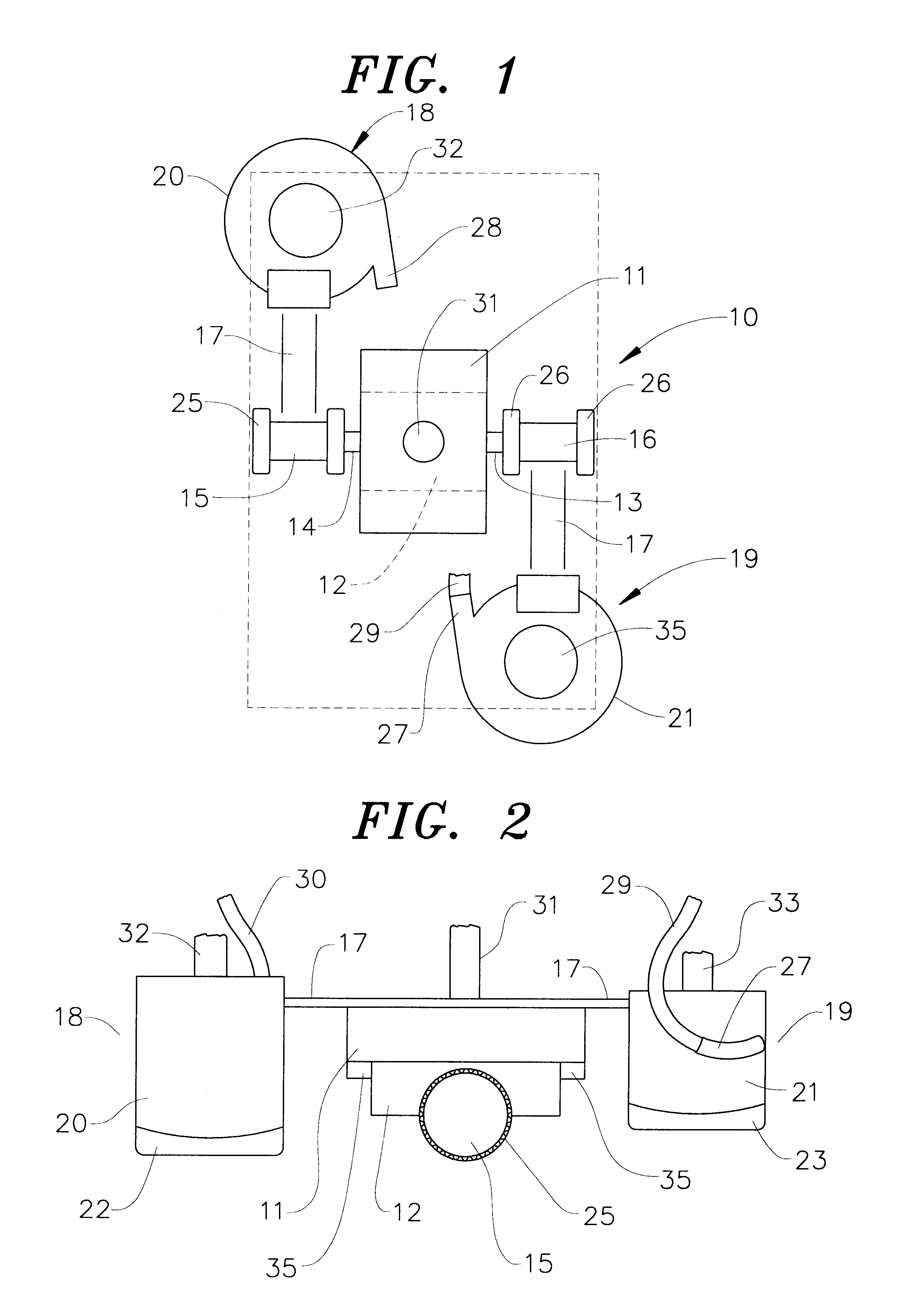
The mobile magnetic robot 10, shown in FIG. 1, has a power module made up of a motor 11 and transaxle unit 12. The motor may be electric, hydraulic, pneumatic, or fuel burning. As shown, the transaxle is mounted under the motor. However, this relationship may be reversed or the motor and transaxle may be laterally disposed to each other. The transaxle 12 has axle stubs 13 and 14 extending on opposite sides of the unit. Wheels 15 and 16 are removably connected to the axle stubs 13 and 14. The transaxle has the ability to turn one wheel in one direction and the other wheel in the opposite direction, simultaneously, to spin the robot in its own length. The transaxle can also stop one wheel while the other is turning to change direction of the path of the robot. The power module may be controlled remotely by wire or wireless signaling from a computer or manual controller 7 to maneuver the robot to traverse the entire surface of the work piece. Alternatively or additionally, the power mo...


PUM


Abstract

A mobile robot for cleaning, stripping, reconditioning or refurbishing a coating on a metal work piece has a remote controlled power module for locomotion and a working head for removing the coating. The robot is held on the metal work piece by magnets mounted on the robot but spaced from the work piece.

Description

This invention is directed to a mobile robot that, by magnetic force, maintains operational contact with metal surfaces of the work piece over which it moves. The robot carries magnets displaced from the work piece an optimal distance related to the maximum magnetic flux between the robot and the work piece.The robot carries attachments to strip, clean, refurbish and / or recondition the surface as it moves across the work piece. These attachments have structure and subsequent treatments that render the entire operation environmentally safe.The robot can be used to refurbish any stationary or movable structures made of a metal having magnetic properties, such as buildings and vehicles. These structures include but are not limited to any iron or steel clad buildings, bridges, tunnels, pipe lines, ships, trains, cars, trucks, and military vehicles of all types.Mobile robots that have magnetic wheels in contact with the surface upon which they work are conventional. However, the movement...

Claims


Application Information

Patent Timeline
Patent Type & Authority Patents(United States)
IPC IPC(8): B63B59/00B62D57/024B63B59/10B62D57/00B25J5/00
CPCB62D57/024B63B59/10B63B2231/30
Inventor MCGUIRE, DENNIS
Owner DCP WATERJET HLDG INC
Why Eureka
Try Eureka