

Vehicle recycling system and method
a technology for recycling systems and vehicles, applied in metal-working apparatus, manufacturing tools, shaping tools, etc., can solve problems such as inoperable, difficult control of theft and vandalism, and land intensive traditional salvage operations, and achieve the effects of reducing efficiency, reducing labor intensity, and reducing the efficiency of outdoor scrap operations
- Summary
- Abstract
- Description
- Claims
- Application Information
AI Technical Summary
Benefits of technology
Problems solved by technology
Method used
Image

Examples
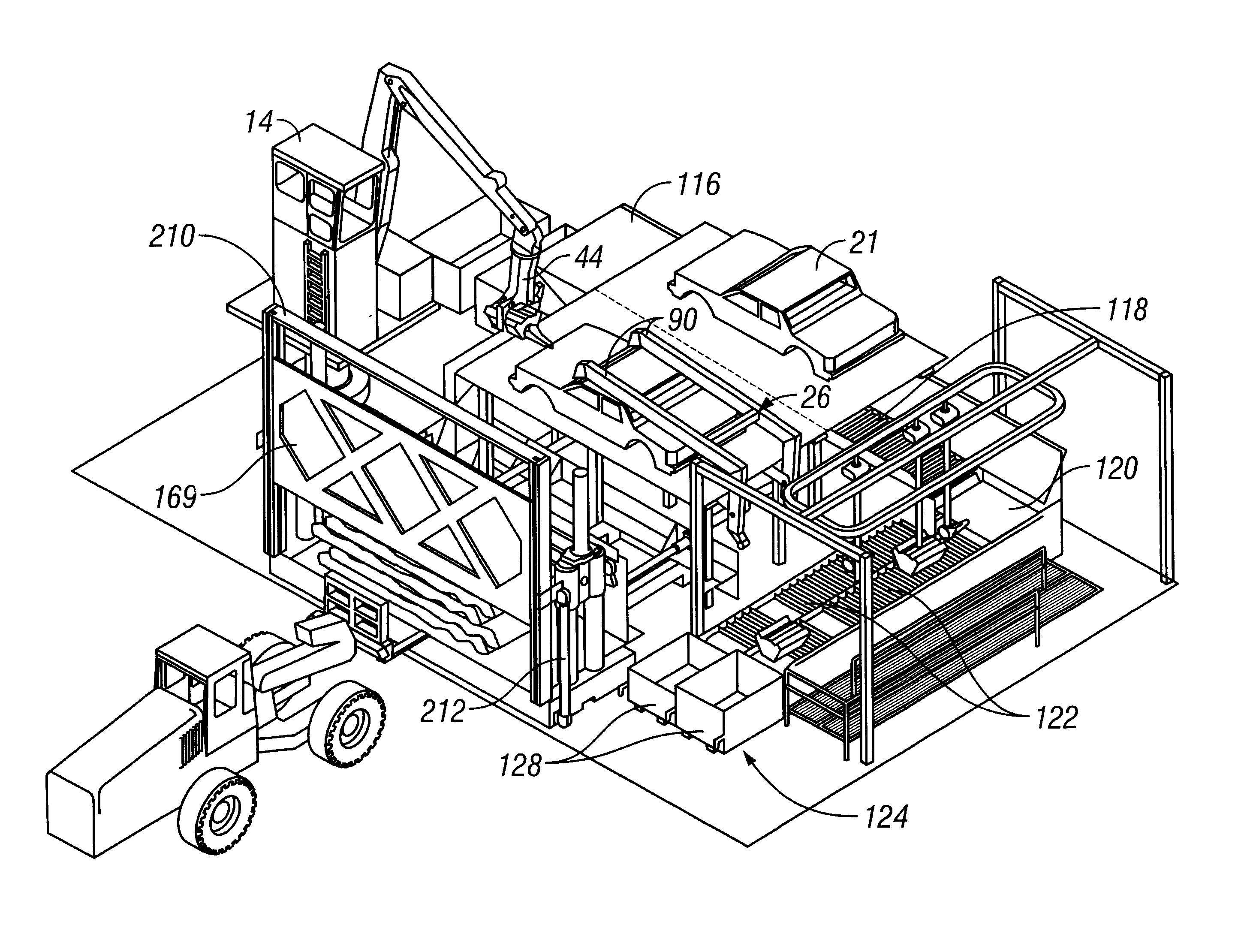
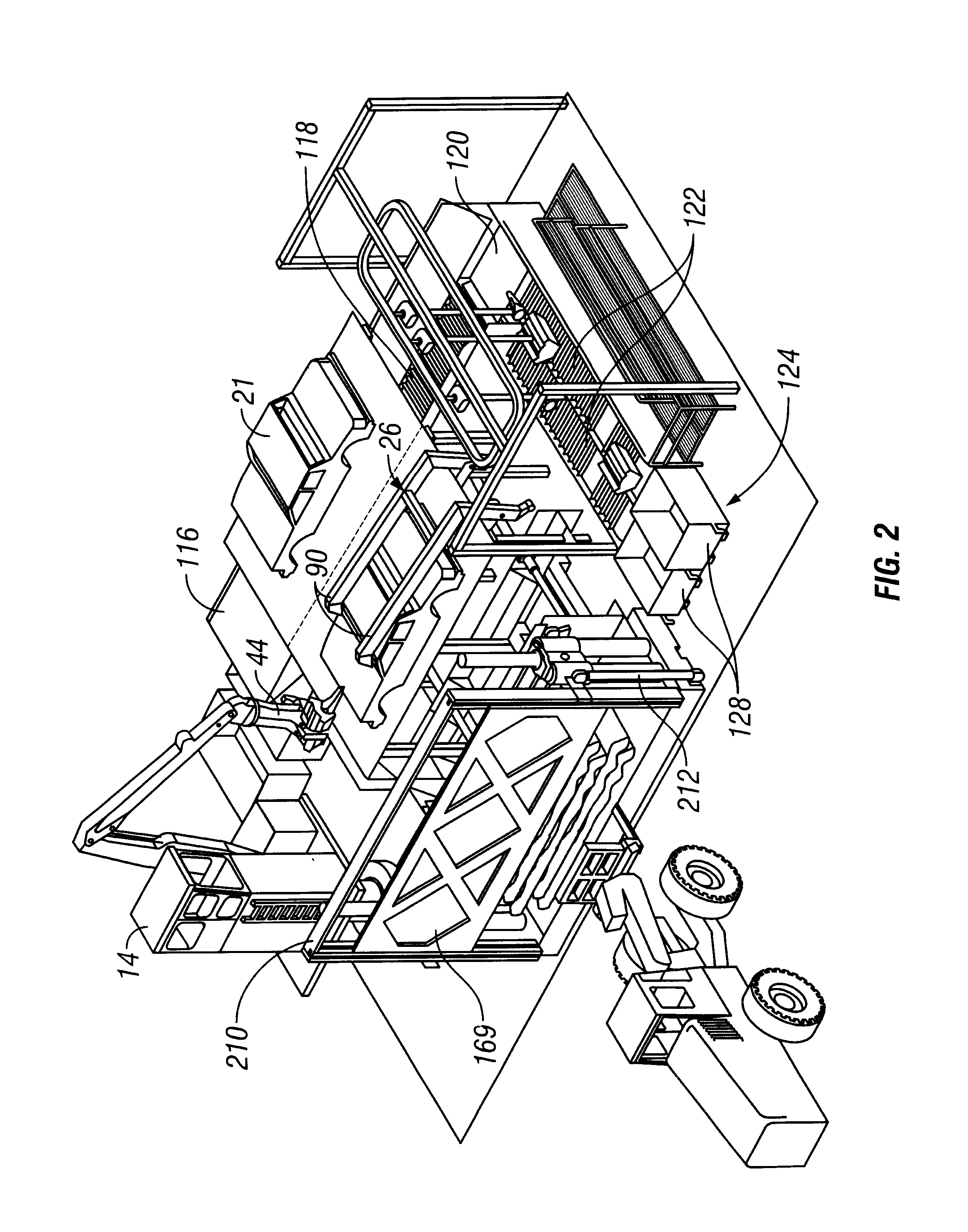
second embodiment
The second embodiment may also include a base assembly 230 to which the individual components are attached. The base assembly 230 serves to stabilize the individual components and fix their positions relative to one another.
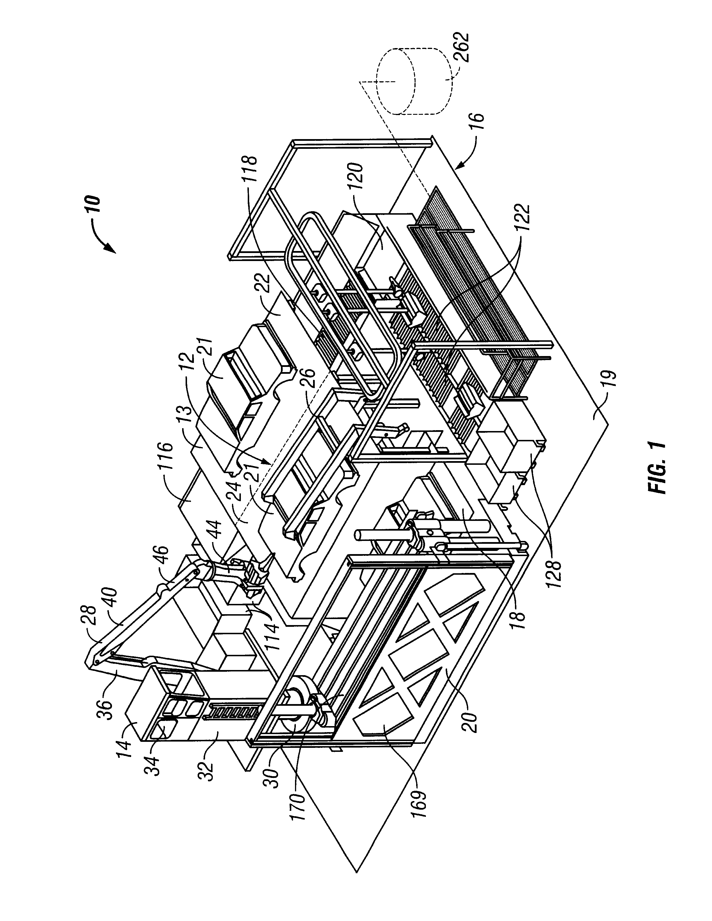
A vehicle system in accordance with the present invention offers several advantages over prior systems. First is the environmental benefit that comes from the recycling operation being moved indoors. Since the system is set on a concrete slab and inside, there are no ground water or rainwater run off issues. Hence this system is in strict compliance with edicts from the National Pollution Discharge Elimination System. Residual fluid is more easily removed and managed. In this respect, system can include a floor drain 260 which is connected to a collection tank 262 so that the waste fluids can be recycled and / or disposed of in accordance with applicable environmental standards (See FIG. 1). The tank can be buried under ground at a location outside of the building ...
PUM
 Abstract
Description
Claims
Application Information