Heat pump cycle

a heat pump and cycle technology, applied in the direction of heat pumps, lighting and heating equipment, electrochemical generators, etc., can solve the problems of unnecessarily increasing power consumption of compressors, reducing the heat quantity (enthalpy) to be extracted from heat pumps, and deteriorating the coefficient of performance of heat pumps

Inactive Publication Date: 2003-06-10
NIPPON SOKEN +1
View PDF4 Cites 35 Cited by
  • Summary
  • Abstract
  • Description
  • Claims
  • Application Information

AI Technical Summary

Benefits of technology

According to the present invention, a heat pump cycle includes a compressor for compressing refrigerant to a pressure higher than critical pressure of refrigerant, a first high-pressure side heat exchanger disposed to perform a heat exchange between refrigerant discharged from the compressor and a first fluid, a second high-pressure side heat exchanger disposed to perform a heat exchange between refrigerant flowing from the first high-pressure side heat exchanger and a second fluid having a temperature lower than that of the first fluid, a decompression unit disposed for controlling the pressure of refrigerant discharged from the compressor and for decompressing refrigerant flowing from the second high-pressure side heat exchanger, and a low-pressure side heat exchanger disposed to evaporate refrigerant decompressed in the decompression unit. Accordingly, a heat quantity obtained in a heat pump of the heat pump cycle becomes the sum of a heat quantity to be extracted in the first high-pressure side heat exchanger and a heat quantity to be extracted in the second high-pressure side heat exchanger. Thus, in the heat pump cycle, it can prevent the heat quantity to be extracted from the heat pump from decreasing and hence the coefficient of performance (COP) of the heat pump from becoming worse.
Preferably, a refrigerant temperature detecting device is disposed for detecting a refrigerant temperature between the first high-pressure side heat exchanger and the second high-pressure side heat exchanger, and the decompression unit controls the refrigerant pressure discharged from the compressor to become equal to or lower than a predetermined pressure based on the refrigerant temperature between the first high-pressure side heat exchanger and the second high-pressure side heat exchanger. Accordingly, the refrigerant pressure discharged from the compressor becomes higher, and the temperature of the first fluid can be sufficiently increased.

Problems solved by technology

In this connection, when the inventors built a prototype of a heat pump cycle for heating hot water in a high-pressure side heat exchanger using the vapor compressing cycle, the following problem occurred.
For this reason, a difference in temperature between the refrigerant and the hot water gradually decreases in the high-pressure side heat exchanger, so that the heat quantity (enthalpy) to be extracted from a heat pump gradually decreases and hence the coefficient of performance (COP) of the heat pump gradually deteriorates.
When the high-pressure side refrigerant temperature is increased to ensure the difference in temperature between the refrigerant and the hot water, a refrigerant pressure is increased more than a necessary refrigerant pressure, and therefore, the power consumption of the compressor increases unnecessarily.

Method used


Image

  • Heat pump cycle
  • Heat pump cycle
  • Heat pump cycle

Examples


first preferred embodiment

(First Preferred Embodiment)

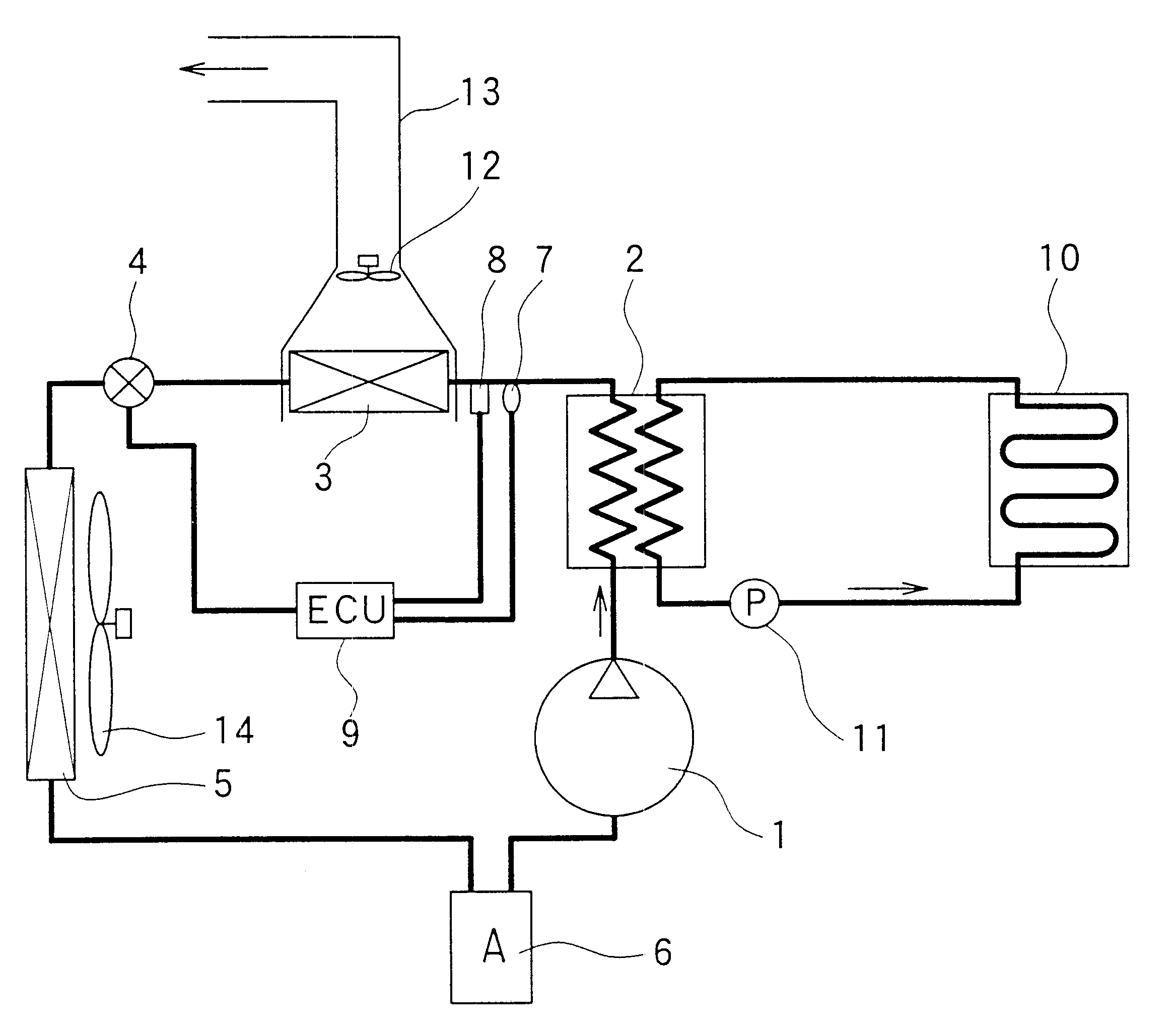
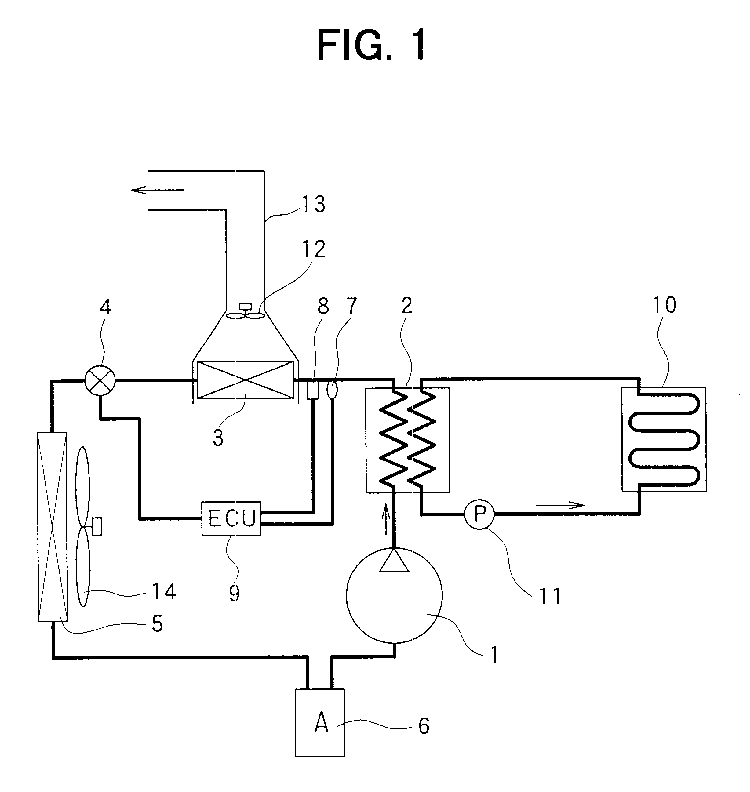
In the first preferred embodiment, a heat pump cycle of the present invention is typically applied to a heating device used for a home. FIG. 1 is a schematic diagram showing a heating device used for the home in accordance with the first embodiment. In the heat pump cycle of FIG. 1, a compressor 1 sucks a refrigerant (e.g., carbon dioxide in the present preferred embodiment) and compresses the refrigerant to a pressure not less than the super-critical pressure of the refrigerant. A first high-pressure side heat exchanger 2 is disposed to perform a heat exchange between a high pressure refrigerant discharged from the compressor 1 and hot water supplied for heating a floor (hereinafter referred to as hot water).

A second high-pressure side heat exchanger (supplementary heat exchanger) 3 is disposed to perform a heat exchange between the high pressure refrigerant flowing out from the first high-pressure side heat exchanger 2 and air blown into a bathroom (not...

second preferred embodiment

(Second Preferred Embodiment)

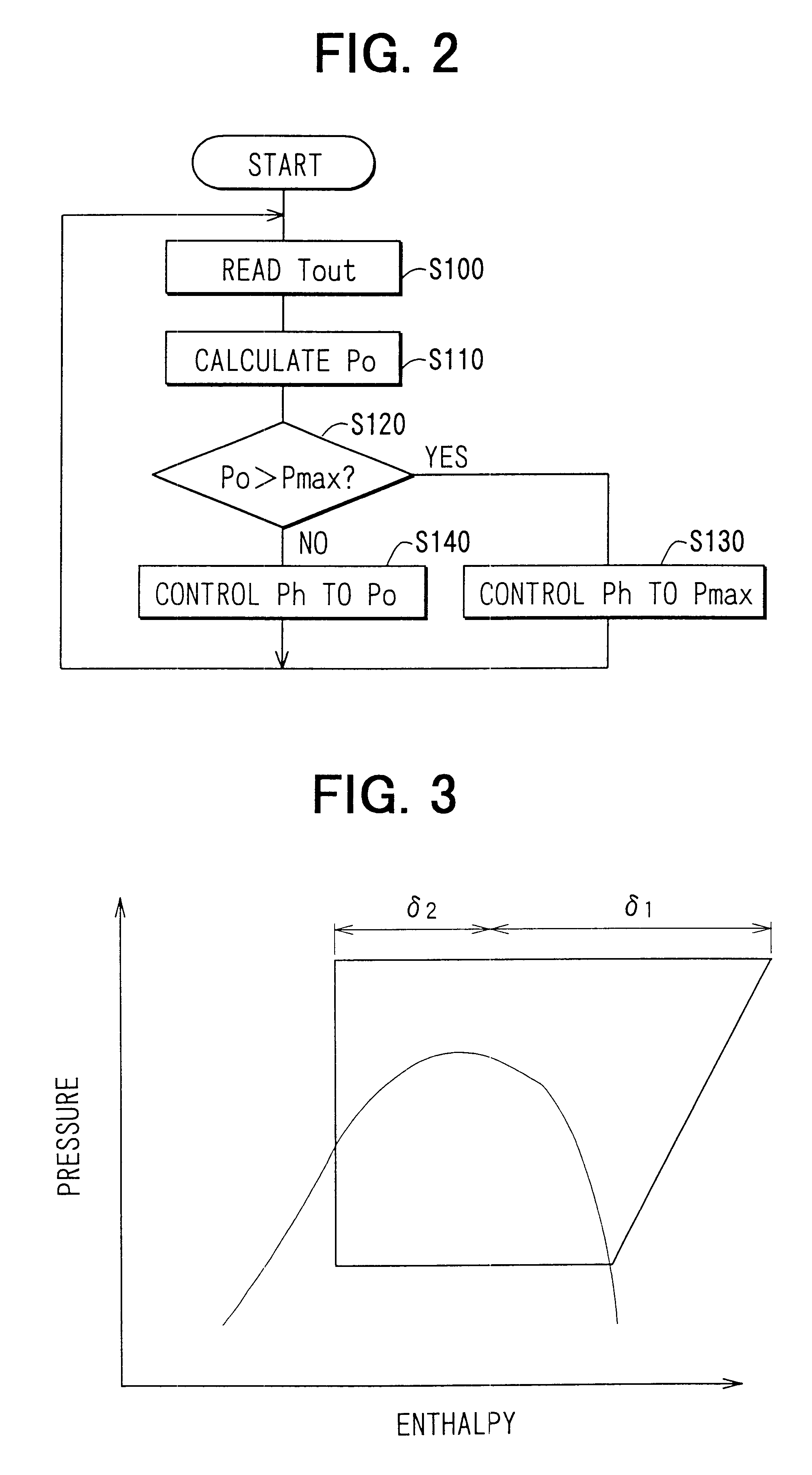
In the above-described first embodiment, the permissible maximum pressure Pmax is fixed at a specific value. However, in the second embodiment, the permissible maximum pressure Pmax is changed based on outside air temperature. The permissible maximum pressure Pmax also can be changed based on the refrigerant pressure (evaporation pressure) in the low-pressure side heat exchanger 5 or the refrigerant temperature (evaporation temperature) in the low-pressure side heat exchanger 5. Here, the permissible maximum pressure Pmax can be set to become higher in accordance with an increase of the evaporation pressure or the evaporation temperature in the low-pressure side heat exchanger 5.

That is, the temperature of refrigerant discharged from the compressor 1 is determined by the discharge pressure (high-pressure side refrigerant pressure) of refrigerant discharged from the compressor 1 and the refrigerant temperature (i.e., evaporation temperature) sucked into t...

third preferred embodiment

(Third Preferred Embodiment)

In the third embodiment, the heat pump in accordance with the present invention is used for heating in a vehicle heater and in a fuel cell (FC stack). FIG. 7 is a schematic diagram of a heat pump cycle in accordance with the third embodiment. Hereinafter, the points different with the above-described first and second preferred embodiments will be now described.

In FIG. 7, there are provided fuel cells (FC stack) 20 for generating electricity by chemically reacting hydrogen with oxygen, and first and second pumps 21, 22 for circulating hot water (cooling water).

The cooling water for cooling the FC stack 20 flows from the FC stack 20, and is cooled by a radiator 23. Further, a bypass circuit 24, through which the cooling water flowing out from the FC stack 20 bypasses the radiator 23 and return to the FC stack 20, is provided. The quantity of the cooling water passing through the radiator 23 and the quantity of the cooling water passing through the bypass ci...


PUM

PropertyMeasurementUnit
densityaaaaaaaaaa
heat resistance temperatureaaaaaaaaaa
temperatureaaaaaaaaaa

Abstract

In a heat pump cycle, a first high-pressure side heat exchanger is disposed to perform a heat exchange between refrigerant discharged from a compressor and a first fluid, and a second high-pressure side heat exchanger is disposed to perform a heat exchanger between refrigerant from the first high-pressure side heat exchanger and a second fluid having a temperature lower than that of the first fluid. Accordingly, a heat quantity obtained from the heat pump cycle is the sum of a heat amount obtained from the first high-pressure side heat exchanger and a heat amount obtained from the second high-pressure side heat exchanger.

Description

This application is related to Japanese Patent Applications No. 2000-220910 filed on Jul. 21, 2000, and No. 2001-120160 filed on Apr. 18, 2001, the contents of which are hereby incorporated by reference.1. Field of the InventionThe present invention relates to a super-critical (trans-critical) heat pump in which a discharge pressure of refrigerant from a compressor exceeds the critical pressure of the refrigerant in a heat pump cycle for transferring heat in a low temperature side to a high temperature side, and is effectively applied to the one using carbon dioxide as a refrigerant.2. Description of Related ArtIn a vapor compressing cycle described in U.S. Pat. No. 5,890,370, a discharge pressure of refrigerant from a compressor exceeds the critical pressure of refrigerant, and a high-pressure side refrigerant pressure is controlled based on a refrigerant temperature at an outlet side of a radiator (high-pressure side heat exchanger). In this connection, when the inventors built a ...

Claims


Application Information

Patent Timeline
Patent Type & Authority Patents(United States)
IPC IPC(8): B60H1/00F25B6/00F25B6/04F25B13/00F25B9/00F25B30/02F25B30/00B60H1/22F25B1/00H01M8/00H01M8/04H01M8/10
CPCB60H1/00792F25B6/04F25B9/008F25B13/00F25B30/02B60L1/003B60H1/00907B60L2270/46B60H2001/00949F25B2309/061F25B2313/02791F25B2339/047F25B2500/26F25B2600/0271F25B2600/17F25B2700/195F25B2700/2106F25B2700/2116B60H2001/00935
Inventor OZAKI, YUKIKATSUHOTTA, TADASHIYAMAGUCHI, MOTOHIROYAMANAKA, YASUSHI
Owner NIPPON SOKEN
Why Eureka
Try Eureka