Heat Pump Cycle

a heat pump and cycle technology, applied in the direction of heat pumps, lighting and heating equipment, electrochemical generators, etc., can solve the problems of unnecessarily increasing power consumption of compressors, reducing the heat quantity (enthalpy) to be extracted from heat pumps, and deteriorating the coefficient of performance of heat pumps

Inactive Publication Date: 2002-01-24
NIPPON SOKEN +1
View PDF0 Cites 44 Cited by
  • Summary
  • Abstract
  • Description
  • Claims
  • Application Information

AI Technical Summary

Problems solved by technology

In this connection, when the inventors built a prototype of a heat pump cycle for heating hot water in a high-pressure side heat exchanger using the vapor compressing cycle, the following problem occurred.
For this reason, a difference in temperature between the refrigerant and the hot water gradually decreases in the high-pressure side heat exchanger, so that the heat quantity (enthalpy) to be extracted from a heat pump gradually decreases and hence the coefficient of performance (COP) of the heat pump gradually deteriorates.
When the high-pressure side refrigerant temperature is increased to ensure the difference in temperature between the refrigerant and the hot water, a refrigerant pressure is increased more than a necessary refrigerant pressure, and therefore, the power consumption of the compressor increases unnecessarily.

Method used


Image

  • Heat Pump Cycle
  • Heat Pump Cycle
  • Heat Pump Cycle

Examples


first embodiment

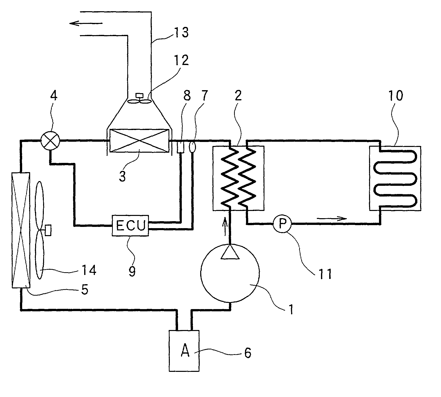
[0032] In the first preferred embodiment, a heat pump cycle of the present invention is typically applied to a heating device used for a home. FIG. 1 is a schematic diagram showing a heating device used for the home in accordance with the In the heat pump cycle of FIG. 1, a compressor 1 sucks a refrigerant (e.g., carbon dioxide in the present preferred embodiment) and compresses the refrigerant to a pressure not less than the super-critical pressure of the refrigerant. A first high-pressure side heat exchanger 2 is disposed to perform a heat exchange between a high pressure refrigerant discharged from the compressor 1 and hot water supplied for heating a floor (hereinafter referred to as hot water).

[0033] A second high-pressure side heat exchanger (supplementary heat exchanger) 3 is disposed to perform a heat exchange between the high pressure refrigerant flowing out from the first high-pressure side heat exchanger 2 and air blown into a bathroom (not shown). An electronic pressure...

second embodiment

[0054] Accordingly, in the second embodiment, the permissible maximum pressure Pmax is changed so that the permissible maximum pressure Pmax increases in response to an increase in the evaporation pressure (outside air temperature) in the low-pressure side heat exchanger 5. Accordingly, the pressure control valve 4 is controlled to sufficiently heat the hot water and to make the refrigerant temperature discharged from the compressor 1 lower than the heat-resistance temperature of the compressor 1.

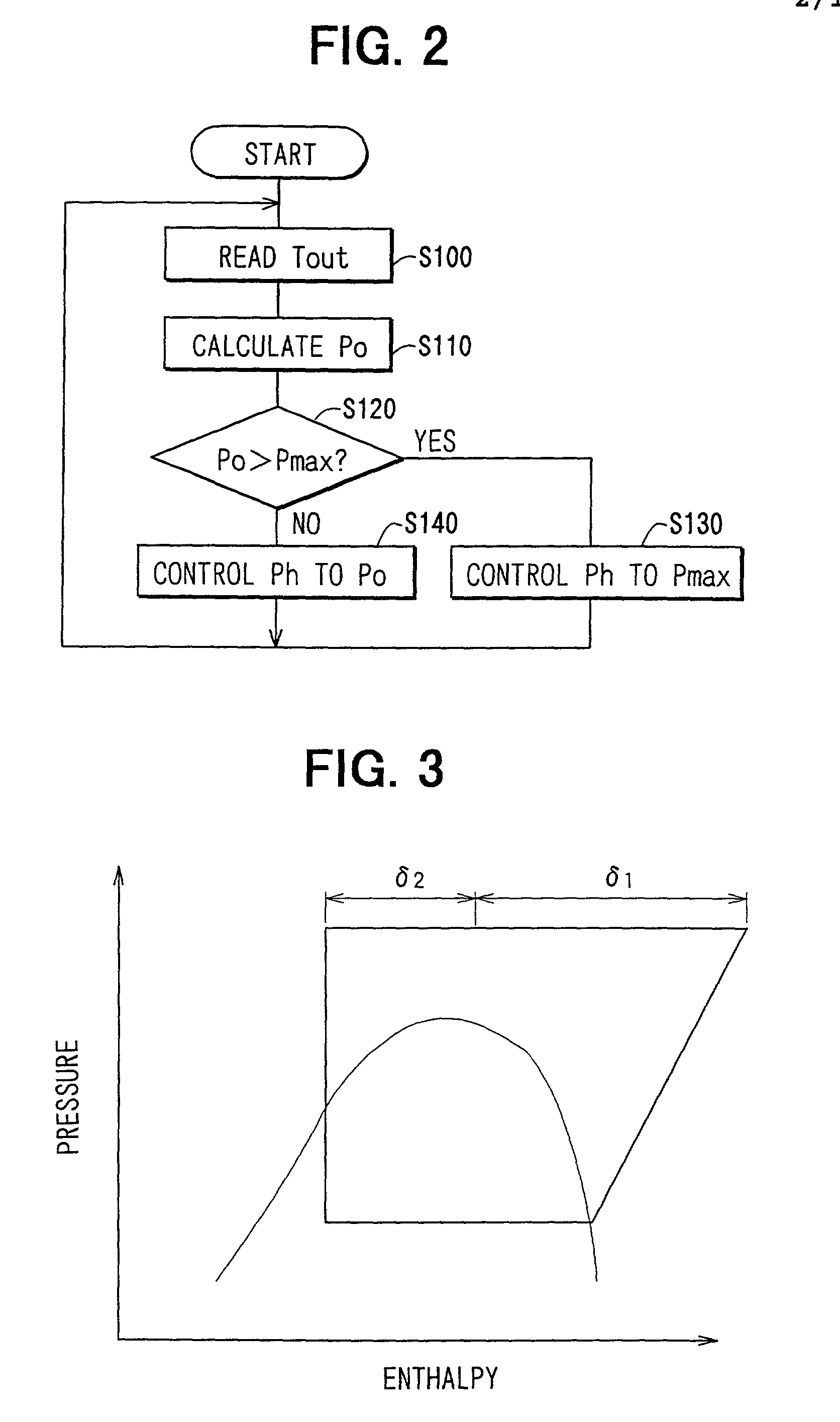
[0055] The control operation of a heat pump cycle according to the second embodiment will be described based on the flow diagram shown in FIG. 6.

[0056] When the starting switch of the heat pump is turned on, first, the high-pressure side refrigerant temperature Tout is read at step S200 by using the refrigerant temperature sensor 7 (see FIG. 1) and the target high-pressure side refrigerant pressure Po corresponding to the high-pressure side refrigerant temperature Tout is calculated based o...

third embodiment

[0066] In the third embodiment, the first high-pressure side heat exchanger 2 is arranged at a downstream water side of the hot-water heater 30 and heats the hot water flowing into the FC stack 20, and the second high-pressure side heat exchanger 3 is arranged at the upstream air side of the hot-water heater 30 in the casing 32, and heats air flowing into the passenger compartment.

[0067] Next, the operation of a heat pump cycle according to the third embodiment will be described.

[0068] (1) Warming-up operation of the FC stack 20

[0069] When the temperature of the FC stack 20 is low, in order to start the operation of the FC stack 20, the FC stack 20 needs to be heated to increase its temperature (to be warmed up). Therefore, in order to warm up the FC stack 20, the core surface (portion through which air passes) of the hot-water heater 30 is closed by the warm air adjustment door 31 so that air blowing toward the passenger compartment does not pass through the hot-water heater 30. In...


PUM

PropertyMeasurementUnit
densityaaaaaaaaaa
heat resistance temperatureaaaaaaaaaa
temperatureaaaaaaaaaa

Abstract

In a heat pump cycle, a first high-pressure side heat exchanger is disposed to perform a heat exchange between refrigerant discharged from a compressor and a first fluid, and a second high-pressure side heat exchanger is disposed to perform a heat exchanger between refrigerant from the first high-pressure side heat exchanger and a second fluid having a temperature lower than that of the first fluid. Accordingly, a heat quantity obtained from the heat pump cycle is the sum of a heat amount obtained from the first high-pressure side heat exchanger and a heat amount obtained from the second high-pressure side heat exchanger.

Description

[0001] This application is related to Japanese Patent Applications No. 2000-220910 filed on Jul. 21, 2000, and No. 2001-120160 filed on Apr. 18, 2001, the contents of which are hereby incorporated by reference.[0002] 1. Field of the Invention[0003] The present invention relates to a super-critical (trans-critical) heat pump in which a discharge pressure of refrigerant from a compressor exceeds the critical pressure of the refrigerant in a heat pump cycle for transferring heat in a low temperature side to a high temperature side, and is effectively applied to the one using carbon dioxide as a refrigerant.[0004] 2. Description of Related Art[0005] In a vapor compressing cycle described in U.S. Pat. No. 5,890,370, a discharge pressure of refrigerant from a compressor exceeds the critical pressure of refrigerant, and a high-pressure side refrigerant pressure is controlled based on a refrigerant temperature at an outlet side of a radiator (high-pressure side heat exchanger). In this conn...

Claims


Application Information

Patent Timeline
Patent Type & Authority Applications(United States)
IPC IPC(8): B60H1/22B60H1/00F25B1/00F25B6/04F25B9/00F25B13/00F25B30/02H01M8/00H01M8/04H01M8/10
CPCB60H1/00792B60L2270/46B60H2001/00949F25B6/04F25B9/008F25B13/00F25B30/02F25B2309/061F25B2313/02791F25B2339/047F25B2500/26F25B2600/0271F25B2600/17F25B2700/195F25B2700/2106F25B2700/2116B60H2001/00935B60L1/003B60H1/00907
Inventor OZAKI, YUKIKATSUHOTTA, TADASHIYAMAGUCHI, MOTOHIROYAMANAKA, YASUSHIITOH, SATOSHITOMATSU, YOSHITAKA
Owner NIPPON SOKEN
Why Eureka
Try Eureka