Process window based optical proximity correction of lithographic images

a technology of optical proximity and lithographic images, applied in the field of semiconductor fabrication, can solve the problems of calculating exact correction values, limiting the usefulness of non-iterative rules-based opc, and the circuit image on the photomask may not be precisely reproduced on the substrate, etc., to achieve the maximum usable range of exposure dose and focus conditions

Inactive Publication Date: 2003-06-10
GLOBALFOUNDRIES U S INC
View PDF22 Cites 297 Cited by
  • Summary
  • Abstract
  • Description
  • Claims
  • Application Information

AI Technical Summary

Benefits of technology

It is yet another object of the invention to provide a proximity correction technique that recognizes the fact that conditions in an IC manufacturing process fluctuate and that chip designs function over a finite range of dimensional variations.
In another aspect, the present invention provides a method of creating a pattern for a mask adapted for use in lithographic production of integrated circuits on a semiconductor substrate, wherein the method comprises providing a mask pattern of a feature to be created on the semiconductor substrate using the mask, and modifying lithography process exposure dose and focus conditions and / or the mask pattern to maximize the usable range of exposure dose and focus conditions in the lithographic production.

Problems solved by technology

The circuit image on the photomask may not be reproduced precisely on the substrate, in part because of optical effects among transmitted and blocked energy passing through the photomask.
While proven to be very efficient at correcting some important one- and two-dimensional imaging problems, non-iterative rules-based OPC is generally believed limited in its usefulness due to the finite number of rules that are available to describe all layout situations, the difficulty of calculating exact correction values based on measured errors, and the lack of feedback loop during the correction process.
Although they have improved pattern replication on wafers, present rules-based and model-based OPC methods still present deficiencies in producing circuit pattern in that their goal is to improve accuracy of pattern replication at one point of the process window (i.e., one dose and focus) rather than optimizing dimensional control over the entire process window (i.e., a large range of dose and focus).

Method used


Image

  • Process window based optical proximity correction of lithographic images
  • Process window based optical proximity correction of lithographic images
  • Process window based optical proximity correction of lithographic images

Examples


Embodiment Construction

)

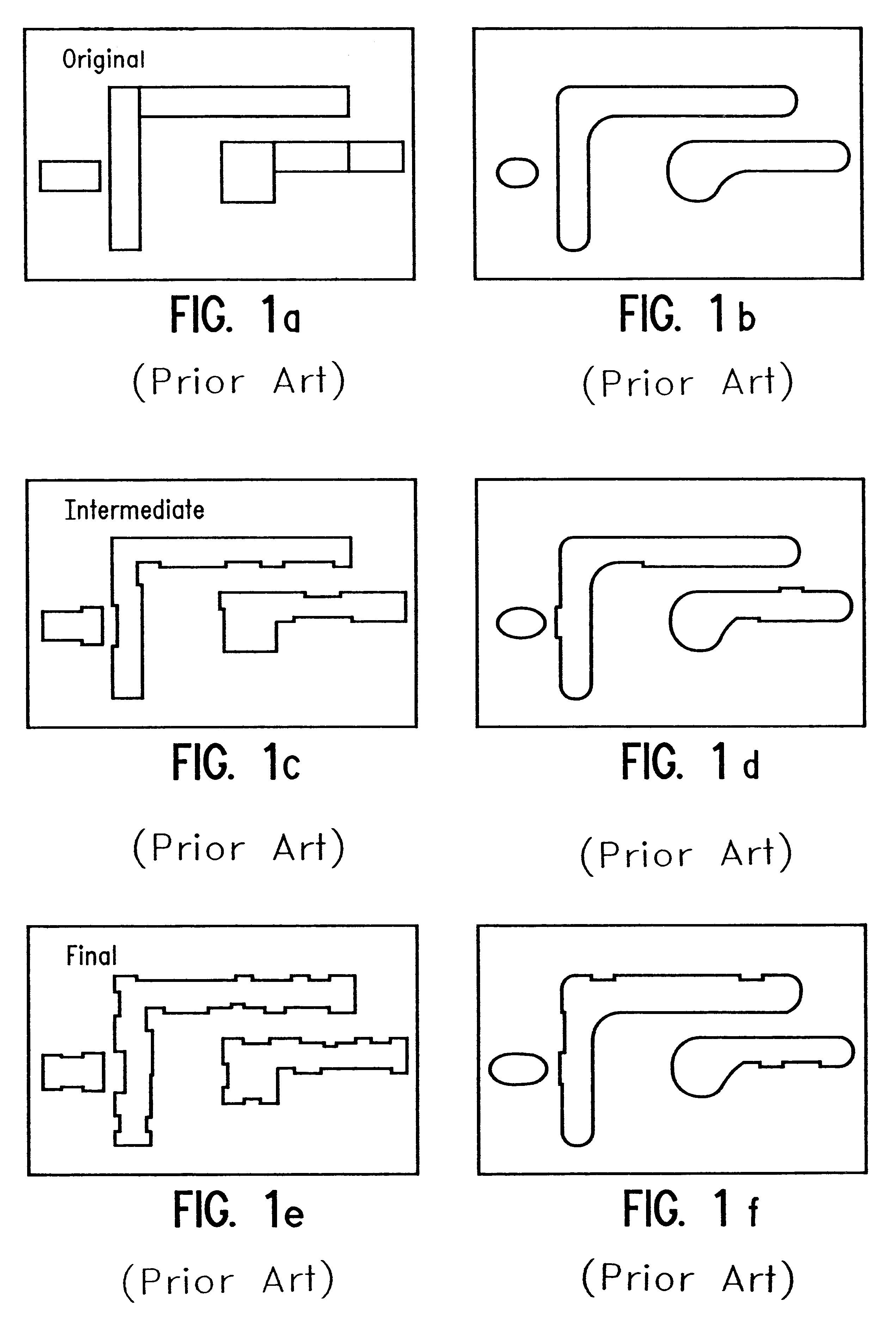
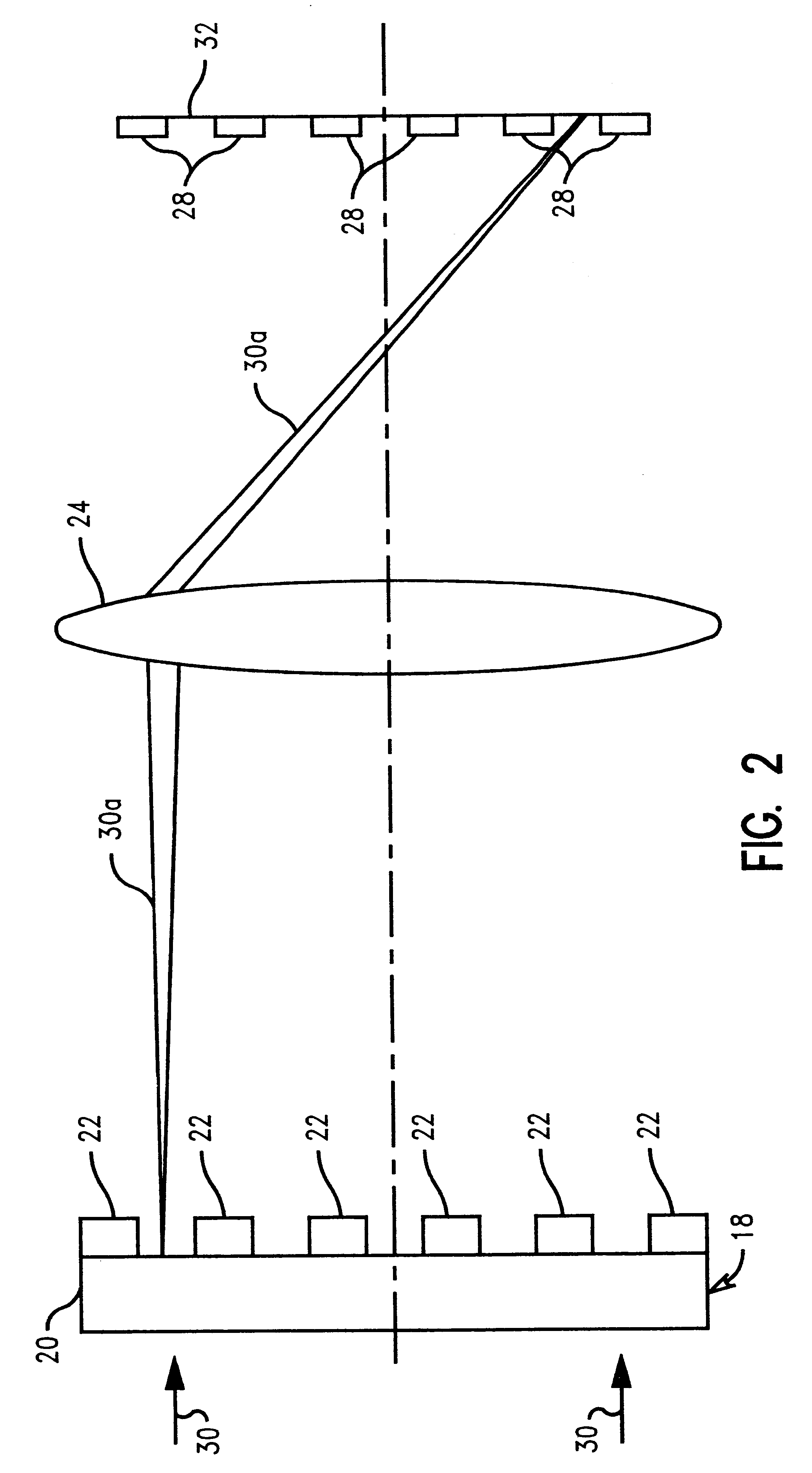
In describing the preferred embodiment of the present invention, reference will be made herein to FIGS. 1-7 of the drawings in which like numerals refer to like features of the invention. Features of the invention are not necessarily shown to scale in the drawings.

The applicants have determined at least two essential problems with commonly implemented model-based OPC tools. The first problem is that the contours of the simulated pattern on which the iterative correction is based are calculated at a single exposure condition, i.e. the modeled image used for OPC represents a snapshot of one possible image which may be obtained for a given process within acceptable values of process fluctuation. In accounting for the fact that the patterning process has certain fluctuations associated with it, there may be built a model based on the average of models calculated for various dose and focus conditions. However, regardless of what technique is used, in the end, the process is described as...


PUM

PropertyMeasurementUnit
total areaaaaaaaaaaa
photosensitiveaaaaaaaaaa
energyaaaaaaaaaa

Abstract

A method of creating a pattern for a mask adapted for use in lithographic production of features on a substrate. The method comprises initially providing a mask pattern of a feature to be created on the substrate using the mask. The method then includes establishing target dimensional bounds of the pattern, determining simulated achievable dimensional bounds of the pattern, comparing the target dimensional bounds of the pattern to the simulated achievable dimensional bounds of the pattern, and determining locations where the simulated achievable dimensional bounds of the pattern differ from the target dimensional bounds of the pattern. In its preferred embodiment, the feature is an integrated circuit to be lithographically produced on a semiconductor substrate.

Description

1. Field of the InventionThis invention relates to semiconductor fabrication and, in particular, to an improved method for creating a mask pattern of an integrated circuit (IC) for use in lithographic processing.2. Description of Related ArtIntegrated circuits are fabricated by lithographic techniques, where energy beams transmit integrated circuit images or patterns on photomasks to photosensitive resists on semiconductor wafer substrates. The circuit image on the photomask may not be reproduced precisely on the substrate, in part because of optical effects among transmitted and blocked energy passing through the photomask.Optical Proximity Correction (OPC) has been employed as a key enabling resolution enhancement technique required to meet image size control requirements imposed by state-of-the-art integrated circuit product programs. OPC is essentially the deliberate and proactive distortion of photomask patterns to compensate for systematic and stable errors. OPC is generally c...

Claims


Application Information

Patent Timeline
Patent Type & Authority Patents(United States)
IPC IPC(8): G03F7/20G03F9/02G03F9/00G06K9/74G06F17/50G06F19/00G21K5/00
CPCG03F1/70G03F1/36
Inventor FERGUSON, RICHARD A.LAVIN, MARK A.LIEBMANN, LARS W.WONG, ALFRED K.
Owner GLOBALFOUNDRIES U S INC
Why Eureka
Try Eureka