
Fuel vaporizing and mixing system and method

a fuel vaporization and mixing system technology, applied in the field of fuel combustion and internal combustion engine design, can solve the problems of incompatibility of low-octane fuels, huge pressure and heat between, uncontrollable, violent explosion of unburned parts of the charge,

Inactive Publication Date: 2003-06-17
DIESEL SOLUTIONS
View PDF9 Cites 23 Cited by
  • Summary
  • Abstract
  • Description
  • Claims
  • Application Information

AI Technical Summary

Benefits of technology

It is finally an object of the present invention to provide such a system which is reliable and inexpensive to manufacture.
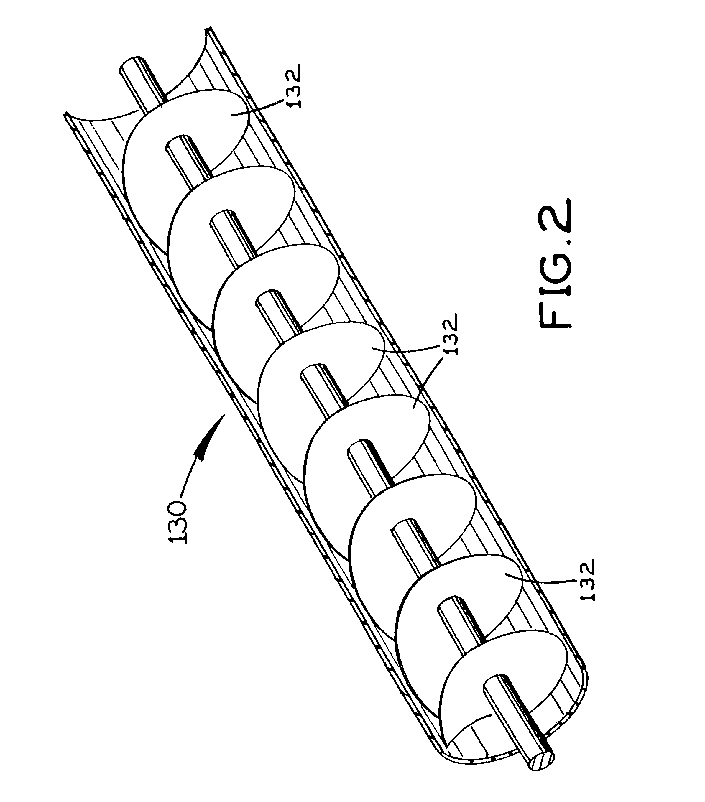
The fuel source is optionally a fuel tank. The fuel vaporization and mixing system preferably additionally includes a fuel blowing mechanism mounted within the vapor collecting chamber for stirring and uniformly distributing fuel vapor. The fuel vaporization and mixing system preferably additionally includes a spiral mixture delivery structure for guiding and efficiently combining the mixture from the molecule mixture box to an internal combustion engine.

Problems solved by technology

"Low-octane fuels are incompatible with high cylinder pressure because they ignite easily.
The two areas of combustion expand, causing tremendous pressure and heat between them.
This results in uncontrolled, violent explosion of the unburned parts of the charge.
This effect, known as detonation, breaks pistons, flattens bearings, and destroys engines.
"Many water injection systems fail to accomplish this because the're really nothing more than squirt guns. . . .[T]hey merely deliver water under pressure to a carburetor without properly aerating it first."
A problem with these prior devices and systems is that none teach or suggest the advantage of combining air and water with fuel which has been vaporized by engine exhaust system heat.

Method used


Image

  • Fuel vaporizing and mixing system and method
  • Fuel vaporizing and mixing system and method
  • Fuel vaporizing and mixing system and method

Examples


Embodiment Construction

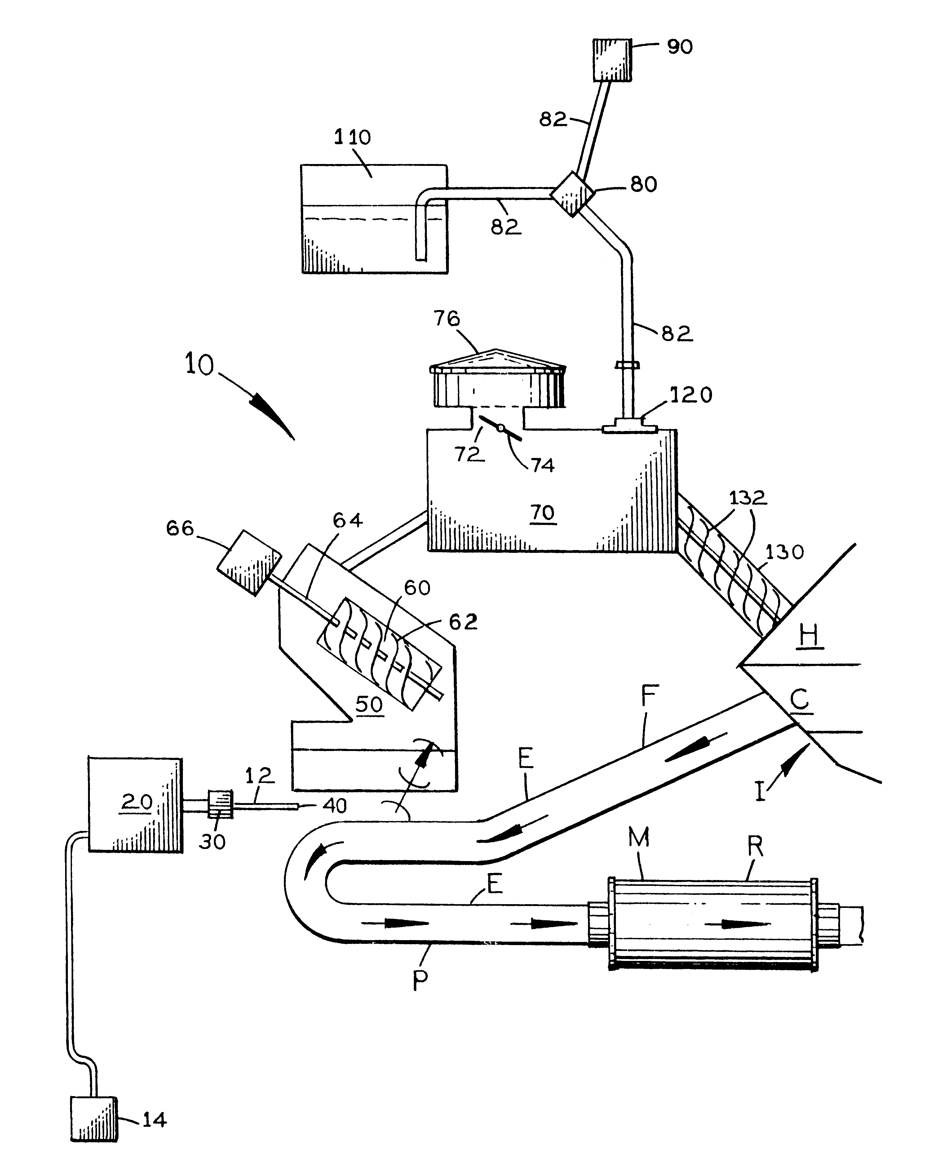
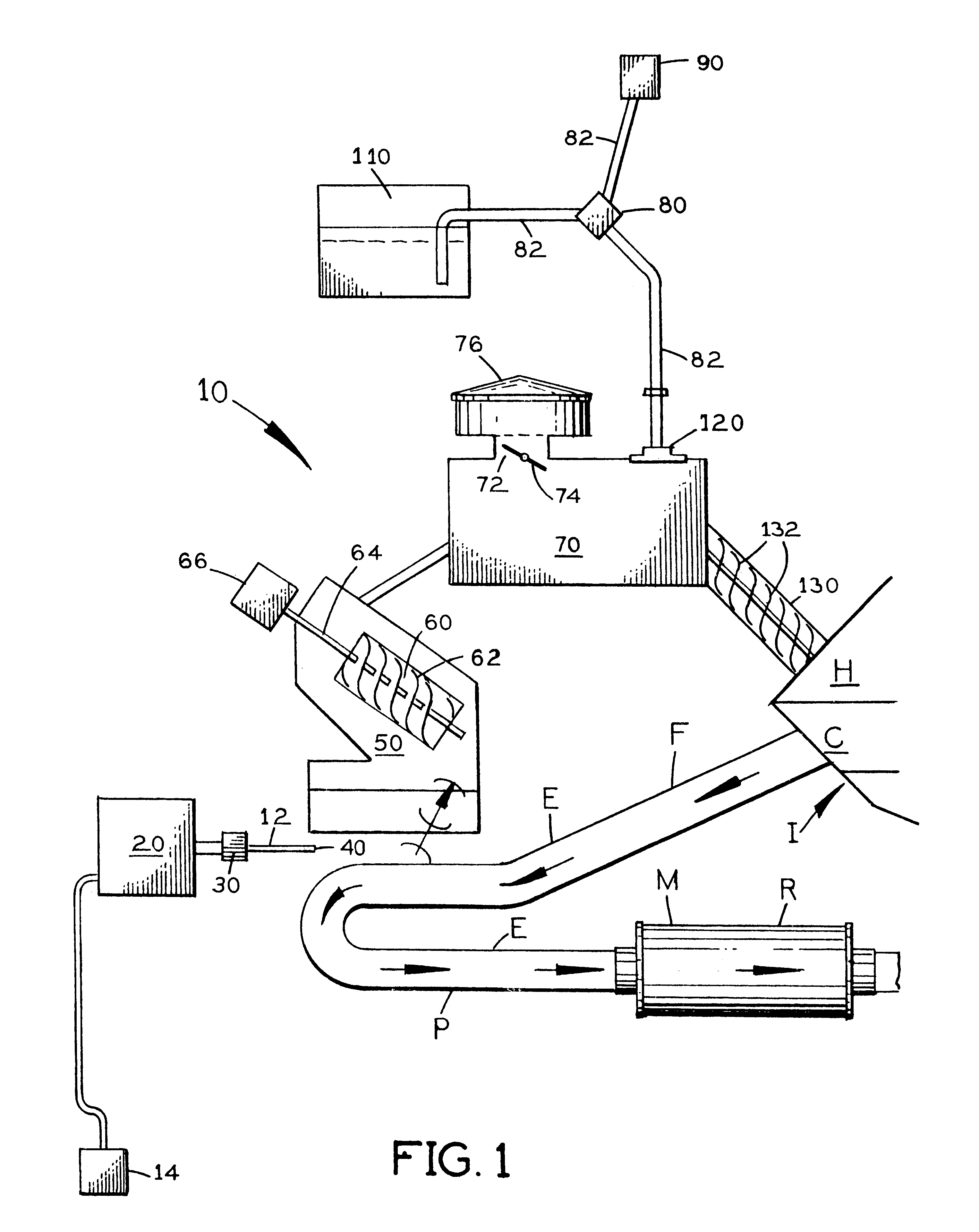
Referring to FIGS. 1 and 2, a fuel vaporization system 10 is disclosed for producing a mixture of fuel vapor, atomized water and air for delivery into an internal combustion engine I, the system 10 being configured and positioned relative to the internal combustion engine I to draw heat from the engine exhaust system E to vaporize fuel for combining into the mixture. The fine atomization of the fuel resulting from the fuel vaporization boosts higher fuel efficiency and causes the engine I to produce significantly more horsepower. The system 10 includes a fuel tank 20 for holding fuel prior to vaporization, a vacuum pump 14 or vacuum drawn off the intake manifold of the engine with a check valve to hold and contain less than atmospheric pressure in fuel tank 20, a fuel pump 30 in fluid communication with the fuel tank 20 for delivering fuel from the fuel tank 20, a fuel metering valve 40 in fluid communication with the fuel pump 30 for metering the flow of fuel from the fuel tank 20,...


PUM


Abstract

A fuel vaporization and mixing system is provided for producing a mixture of fuel vapor, atomized water and air for delivery into an internal combustion engine, the system being configured and positioned relative to the internal combustion engine to draw heat from the engine exhaust system to vaporize fuel for combining into the mixture.

Description

1. Field of the InventionThe present invention relates generally to the field of fuel combustion and internal combustion engine design. More specifically the present invention relates to a fuel vaporization and mixing system for producing a mixture of fuel vapor, atomized water and air for delivery into an internal combustion engine, the system being configured and positioned relative to the internal combustion engine to draw heat from the engine exhaust system to vaporize fuel for combining into the mixture. While it is known that properly combining sprayed fuel and air with atomized water can boost horsepower and fuel efficiency, the automobile industry has failed to recognize that vaporizing the fuel with engine exhaust system heat prior to mixing with air and water is an efficient way of still further enhancing horsepower and fuel mileage.The system includes a fuel tank for holding fuel prior to vaporization and mixing, a fuel pump in fluid communication with the fuel tank for d...

Claims


Application Information

Patent Timeline
IPC IPC(8): F02M29/00F02M29/06F02M31/02F02M31/18
CPCF02M29/06F02M31/18F02M25/035Y02T10/126Y02T10/121Y02T10/12
Inventor ROWLEY, GERALD W.
Owner DIESEL SOLUTIONS
Learn More