Circumferential confronting type motor

a technology of confronting type and motor, which is applied in the direction of magnetic circuit rotating parts, magnetic circuit shape/form/construction, instruments, etc., can solve the problems of motor failure to rotate, bearing life, and escalating parts cos

Inactive Publication Date: 2003-06-17
SANKYO SEIKI MFG CO LTD
View PDF8 Cites 35 Cited by
  • Summary
  • Abstract
  • Description
  • Claims
  • Application Information

AI Technical Summary

Benefits of technology

According to the present invention, due to the fact that the electromagnetic action to rotatively drive the rotor is generated by having the drive magnet and the armature core positioned opposite to each other, and to the fact that the oscillation of the rotor in the thrust direction is restrained by the magnetic action between the plurality of divided magnetized sections, which are formed separated in the axial direction, and the armature core, it is possible to eliminate an independent thrust bearing mechanism that independently supports the rotor in the thrust direction, and thereby reduce the parts cost and the motor price.
With such a structure, since the divided magnetized sections are symmetrically shaped there is no change in the magnetic actions and effects, even when the posture of the drive magnet is inverted vertically. As a result, motor components can be shared, which can reduce the motor price even further.
According to such a structure, the drive magnet comprises two pieces, which is the minimum quantity required to achieve the purpose of the present invention, which are the first divided magnetized section and the second divided magnetizing section. Due to the fact that the attraction directions to the armature core are opposite for the two divided magnetized sections, the oscillation in the axial direction of the drive magnet and the armature core can be regulated relatively with a simple structure.
Furthermore, by mounting the drive magnet on a circumference surface of a magnet yoke and by providing in the magnet yoke and abutting the end surface of the drive magnet a positioning section to position the drive magnet in the axial direction, the drive magnet can be positioned in the axial direction surely and accurately.
When the drive magnet and the armature core are arranged such that one is provided in a rotor assembly while the other is provided in a stator assembly, where the rotor assembly and the stator assembly are supported in a relatively rotatable manner by a radial bearing mechanism comprising a fluid dynamic pressure bearing or an oil-impregnated sintered bearing supported across a predetermined gap, the bearing can wear out or the rotor assembly can stop rotating suddenly when dust enters the gap in structures in which the stator assembly supports the rotor assembly across the predetermined gap, as in fluid dynamic bearings or oil-impregnated sintered bearings. However, according to the present invention, due to the fact that the radial bearing mechanism is provided more interior in the radial direction than the drive magnet, there is an extremely low risk of dust entering the gap, which can lengthen the life of the motor.
According to the present invention, due to the fact that the electromagnetic action to rotatively drive is generated by having the drive magnet and the armature core positioned opposite to each other, and to the fact that the oscillation of the rotor in the thrust direction is restrained by the magnetic action between the plurality of divided magnetized sections and the armature core, it is possible to eliminate an independent thrust bearing mechanism that independently supports the rotor in the thrust direction, and thereby reduce parts cost and the motor price. In addition, dust attached to the drive magnet can be prevented from entering the dynamic pressure bearing mechanism, which makes it possible to sustain the bearing performance for a long time.

Problems solved by technology

Since the dynamic pressure bearing mechanism 4 normally has a bearing gap of several micrometers, once dust enters the bearing gap, so-called bums occur in the dynamic pressure bearing mechanism 4, which can lead to problems in the bearing life and cause major problems such as the motor failing to rotate.
This problem is not limited to motors that use pneumatic dynamic pressure bearings, and can equally occur in motors that use bearings in which the bearing and the shaft are supported in a relatively rotatable manner across a minuscule gap, such as oil dynamic pressure bearings and oil-impregnated sintered bearings.
This can consequently lead to escalating parts cost, which then makes the entire motor expensive.
However, according to the present invention, due to the fact that the radial bearing mechanism is provided more interior in the radial direction than the drive magnet, there is an extremely low risk of dust entering the gap, which can lengthen the life of the motor.

Method used


Image

  • Circumferential confronting type motor
  • Circumferential confronting type motor
  • Circumferential confronting type motor

Examples


embodiment 1

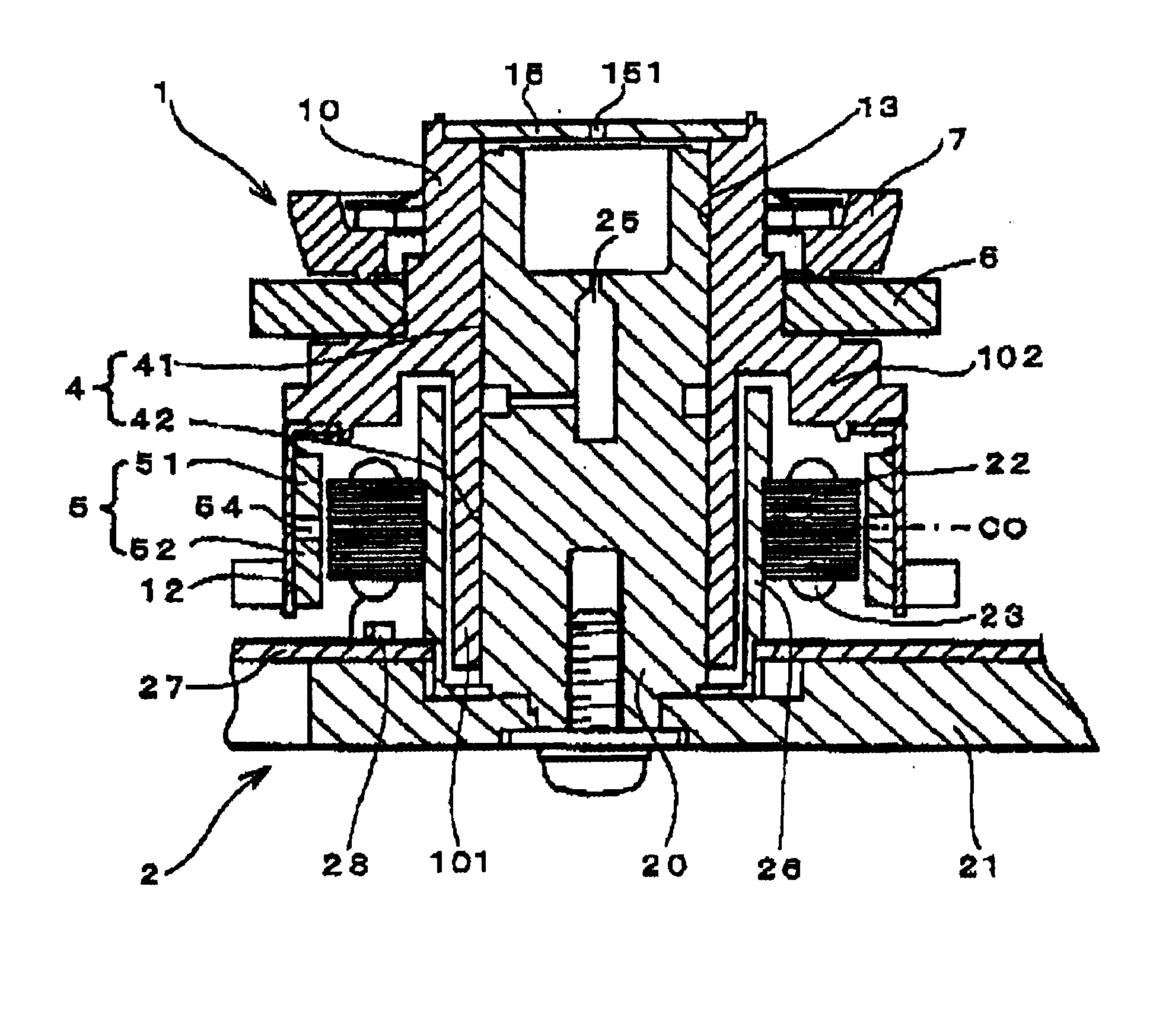
FIG. 1 is a longitudinal cross-sectional view indicating the first embodiment in which a circumferential confronting type motor according to the present invention is applied to a deflection scanning device. The circumferential confronting type motor in FIG. 1 is primarily composed of a rotor assembly 1 and a stator assembly 2. The rotor assembly 1 is equipped with a generally cylindrically-shaped rotor 10, a drive magnet 5 mounted on an outer circumference side of the rotor 10 via a magnet yoke 12, and a polygon mirror 6 fixed to the rotor 10.

The rotor 10 has a cylinder section 101 in which a shaft hole 13 is formed, and a fixed shaft 20 is inserted in the shaft hole 13. An abrasion-resistant film made of electroless nickel plating or hard Alumite film is provided on an inner circumference surface of the shaft hole 13, while on an outer circumference surface of the fixed shaft 20 herringbone-shaped dynamic pressure generating grooves, as well as a lubricating resin film, are formed....

embodiment 2

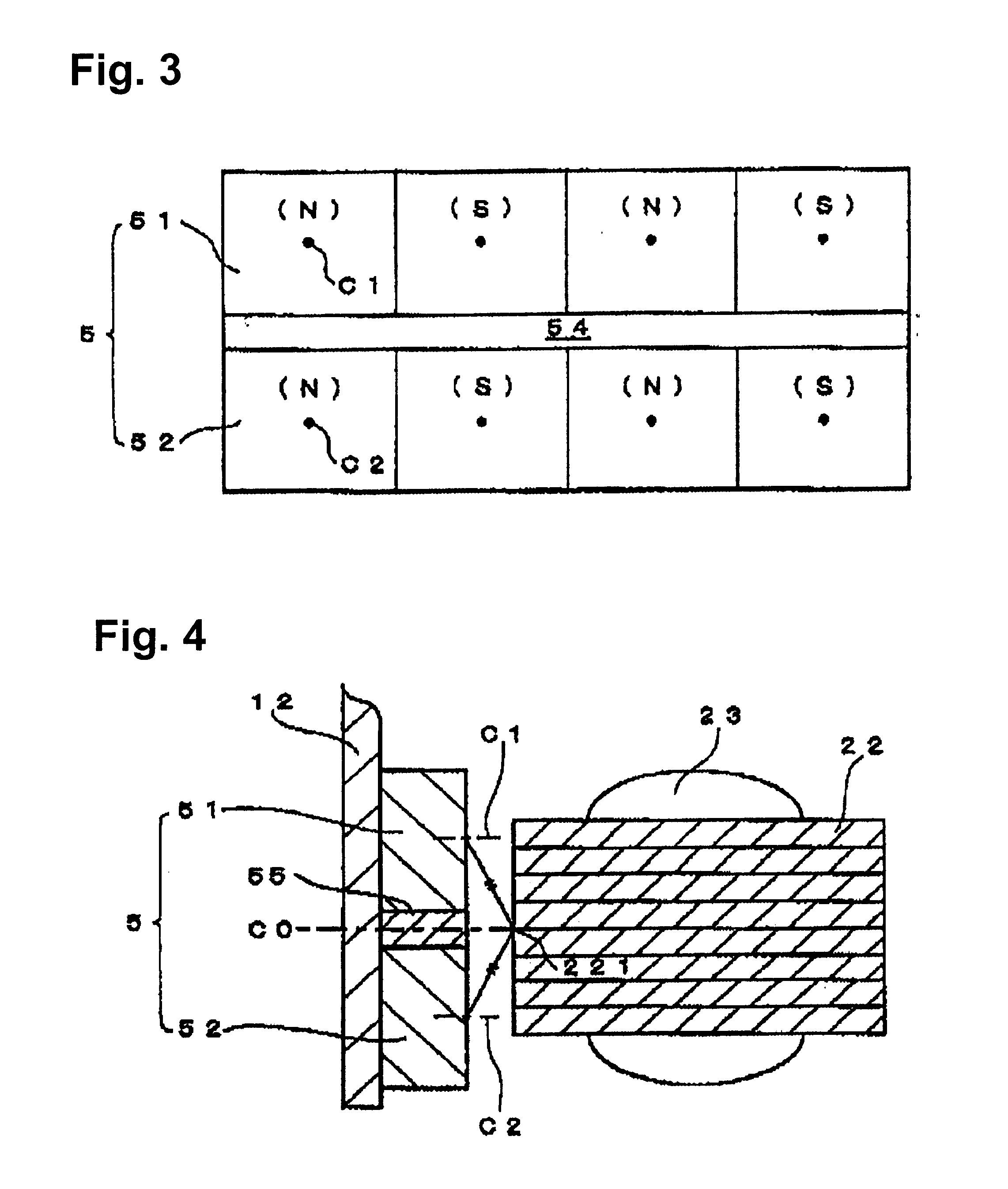
FIGS. 4 and 5 show another embodiment of a circumferential confronting type motor in accordance with the present invention. FIG. 4 is a cross-sectional view of key parts of the circumferential confronting type motor, and FIG. 5 is a developed view of a drive magnet 5. Elements identical to those in the first embodiment are assigned the same numbers and duplicate descriptions are omitted.

In FIG. 4, a drive magnet 5 is equipped with a first divided magnetized section 51 and a second divided magnetized section 52, and the divided magnetized sections are structured as magnets independent from one another across a non-magnetized section 55, which is a void space. The divided magnetized sections 51 and 52 have a magnetic center C1 and a magnetic center C2, respectively, formed at positions symmetrical to a magnetic center C0 in the axial direction of an armature core 22, and the first divided magnetized section 51 and the second divided magnetized section 52 have the same thickness and sh...

embodiment 3

FIG. 6 is a cross-sectional view of key parts of a circumferential confronting type motor in accordance with another embodiment of the present invention. Elements identical to those in the first embodiment are assigned the same numbers and duplicate descriptions are omitted.

In FIG. 6, a drive magnet 5 is mounted on an inner circumference surface of a magnet yoke 12, which has a positioning section 121 that abuts against an end surface 56 of the drive magnet 5 and positions the drive magnet 5 in the axial direction. The positioning section 121 can be easily formed by using a punch from an outer circumference side to an inner circumference side of the magnetic yoke 12, which is made of a magnetic metal, to cause a plastic deformation that protrudes inward in the radial direction. The positioning section 121 can be formed along the entire circumference at the same height in the axial direction of the magnet yoke 12, or it can be formed in a plurality of positions at an interval in the ...


PUM

PropertyMeasurementUnit
skew angleaaaaaaaaaa
magneticaaaaaaaaaa

Abstract

A circumferential confronting type motor includes an armature core that has drive coils wound around its plurality of poles, and a drive magnet positioned opposite to the armature core in the radial direction. The drive magnet has a plurality of divided magnetized sections, each with a magnetic center, formed separated from each other in the axial direction by a non-magnetized section. The magnetic centers of the respective plurality of divided magnetized sections are provided in symmetrical positions with respect to a magnetic center in the axial direction of the armature core. Further, electromagnetic action between the drive magnet and the armature core causes the two to rotate relatively, while magnetic action between the plurality of divided magnetized sections and the armature core regulates their relative movements in the axial direction.

Description

1. Field of the InventionThe present invention relates to a circumferential confronting type motor, in which an armature core and a drive magnet are positioned opposite each other in the radial direction. More specifically, it relates to a thrust bearing mechanism that relatively regulates through magnetic action the movement in the axial direction of a rotor assembly and a stator assembly of the circumferential confronting type motor.2. Description of Related ArtA variety of motors have been proposed that employ a thrust magnetic bearing mechanism in order to stabilize support in the thrust direction of a rotor assembly in a circumferential confronting type motor. FIG. 12 is a cross-sectional view of a prior art that employs a thrust magnetic bearing mechanism in a circumferential confronting type pneumatic dynamic pressure bearing motor used in deflection scanning devices that use polygon mirrors.The pneumatic dynamic pressure bearing motor shown in FIG. 12 comprises primarily of ...

Claims


Application Information

Patent Timeline
Patent Type & Authority Patents(United States)
IPC IPC(8): G11B19/20H02K1/27H02K5/167H02K21/22H02K7/09H02K5/16H02K5/24
CPCG11B19/2009H02K1/2786H02K7/086H02K21/22H02K7/09H02K1/2788
Inventor TAKASU, YOSHIMI
Owner SANKYO SEIKI MFG CO LTD
Why Eureka
Try Eureka