Extrusion devices for mounting wall panels

a technology of extrusion device and wall panel, which is applied in the direction of walls, ceilings, doors/windows, etc., can solve the problems of building failure, affecting the clean appearance of the panel, and the use of conventional extrusion device is rather inconvenient and expensive,

Inactive Publication Date: 2003-07-08
WRIGHT JOHN T
View PDF4 Cites 280 Cited by
  • Summary
  • Abstract
  • Description
  • Claims
  • Application Information

AI Technical Summary

Benefits of technology

In a preferred embodiment, the pocket depth (front cover width) is about 0.50 inch, and the ramp is located about midway in the pocket depth at about 0.25 inch. The extra pocket depth and ramp can give the installer the option to install a thicker panel within the pocket but short of the ramp. Providing the base portion with a long back leg allows the extrusion to deform Slightly so that the thicker panels will fit even if the fastener heads are not countersunk.

Problems solved by technology

However, conventional extrusion devices have been rather inconvenient to use and expensive.
The already-installed caulking must be removed or it will detract from the clean appearance of the panels.
Installers may be tempted to leave out the caulking to facilitate panel repair or removal, but this can lead to panel and building failure due to water seepage through the gaps and into the building walls.
However, these extrusion parts cannot be used to make a clean, rigid fascia / soffit transition or non-standard angle or corner.

Method used


Image

  • Extrusion devices for mounting wall panels
  • Extrusion devices for mounting wall panels
  • Extrusion devices for mounting wall panels

Examples


Embodiment Construction

In the following detailed description, certain preferred embodiments of two-piece and one-piece extrusion devices for mounting wall panels are described. However, it is to be understood that these embodiments are intended only as examples of implementation of the principles of the present invention, and the full scope of the invention is not limited to these examples.

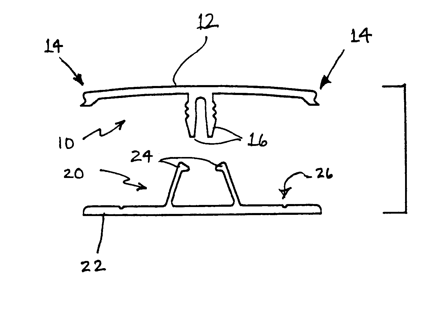
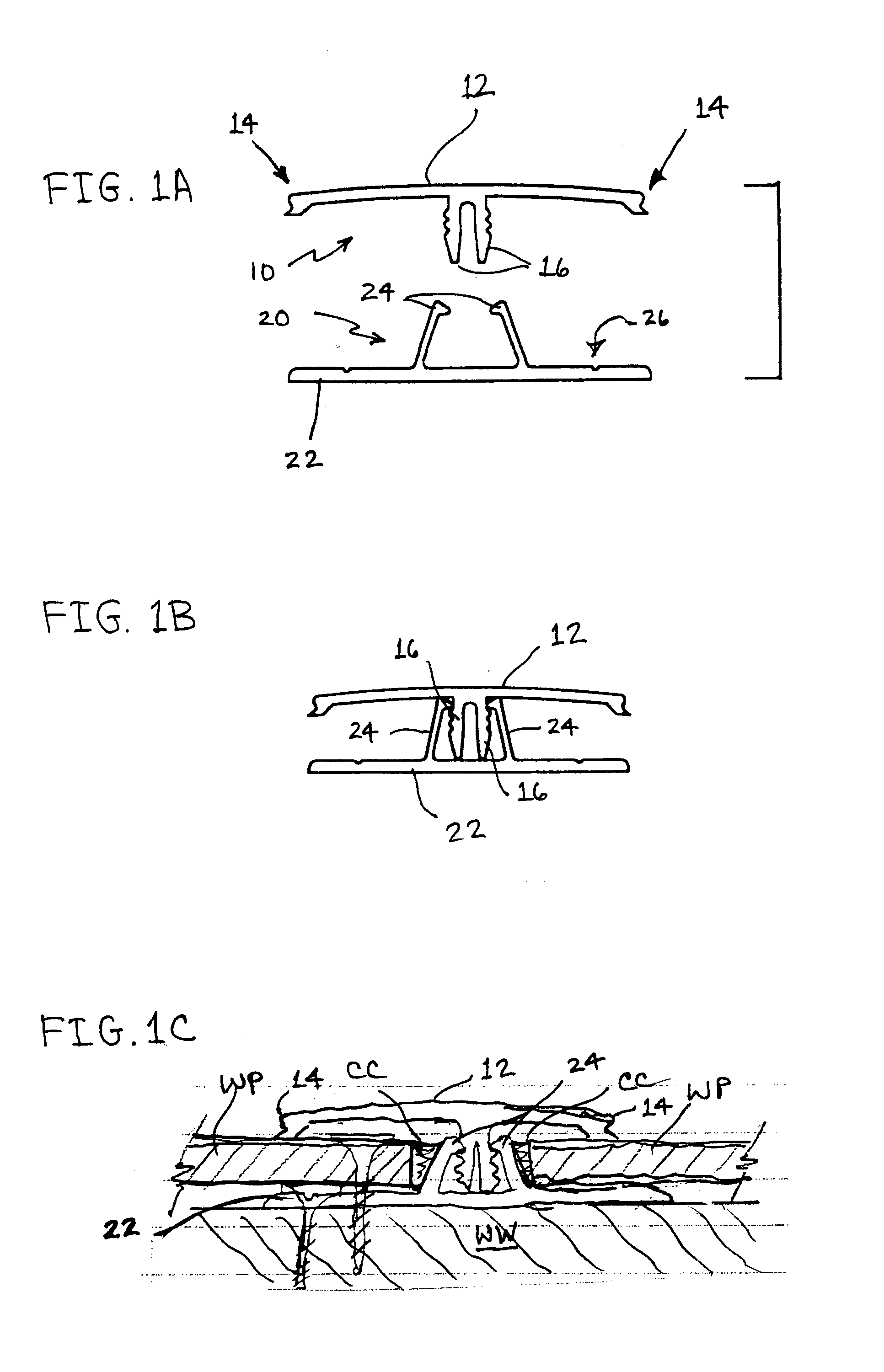
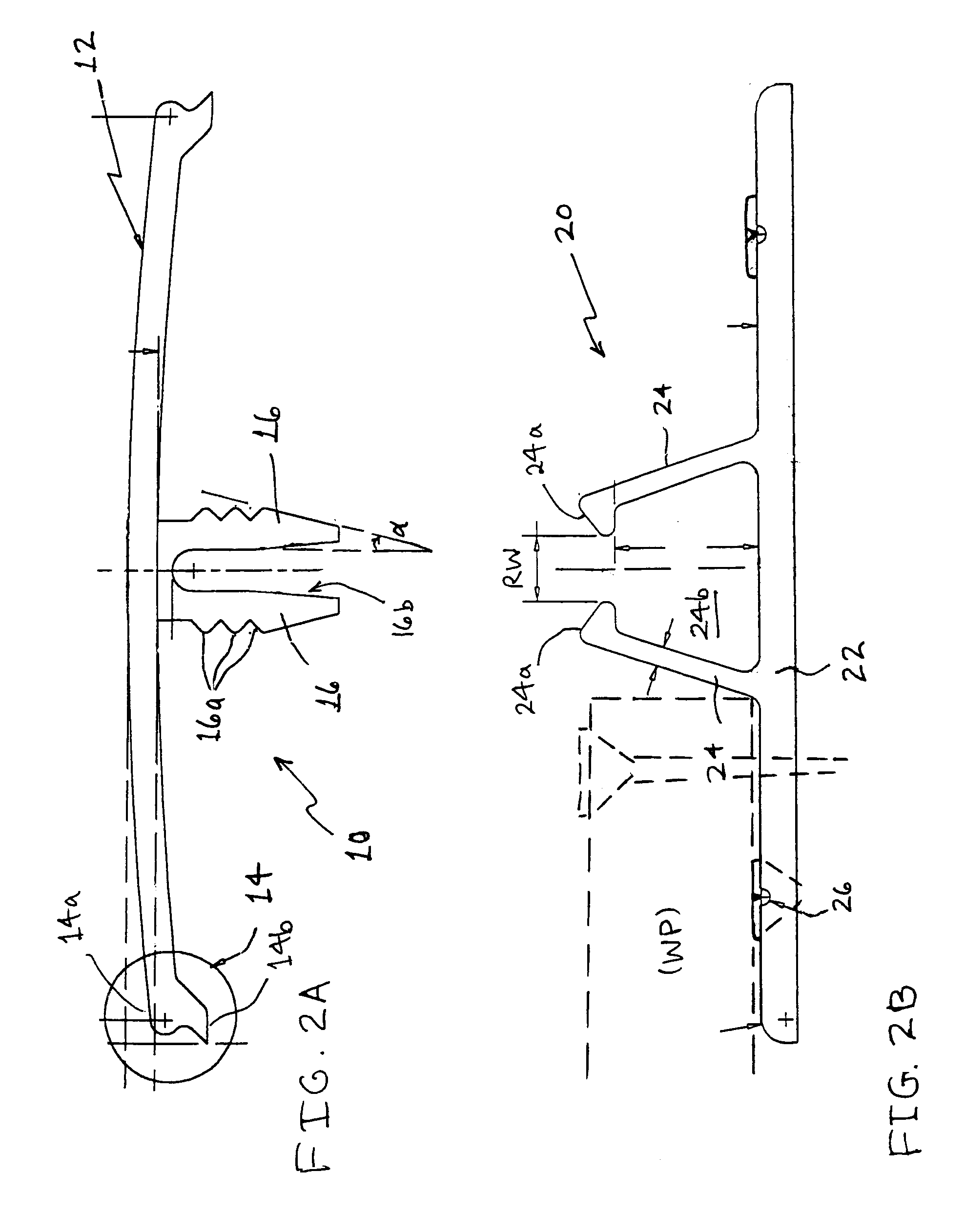
Referring to FIGS. 1A and 1B, a preferred embodiment of a two-piece, straight-type (referred to as "H" type) extrusion is shown having an outer cap 10 provided with a radiused outer surface 12, compound water-shedding edges 14 on opposite lateral sides thereof, and a pair of spaced-apart insertion fingers 16 projecting perpendicularly downward from an inner surface of the cap 10, and an inner receiver base 20 having a planar mounting portion 22 for receiving an end of a wall panel mounted thereon. The receiver base has a pair of angled receiver flanges 24 spaced apart by a given width W and projecting upwardly from a su...


PUM


Abstract

An extrusion device for mounting a wall panel has an outer cap extending to an edge on at least one side which is positioned against an outer surface of a wall panel, having a pair of spaced-apart insertion fingers, and a receiver base having a planar mounting portion and a pair of angled receiver flanges projecting upwardly to receive the insertion fingers therein. The two-piece extrusion permits wall panels to be mounted or removed from the underlying wall structure in on-sequential order. The receiver base and cap can be provided on both sides to form an "H" type extrusion, or on only one side in a "J" type extrusion. Preferably, the outer cap is made of metal, and the tips of the insertion fingers are beveled at a slight angle of about 7° to 14° to allow easy insertion into the receiver flanges. The cap has compound water-shedding edges formed with a rounded rain-drip edge spaced in close proximity to a sharply inclined knife edge. In another variation, a one-piece extrusion device has a rear base portion and a front cover portion forming a pocket therewith, and a ramp formed on the base portion within the width of the front cover portion for gradually forcing the edge of a wall panel inserted in the pocket toward the front cover portion clear of the heads of screws used to mount the base portion to the underlying wall structure. The base portion is formed with a hook indentation on a back side of the ramp on a rear surface of the base portion, and interconnects with a "Z" type extrusion having a hook end to form a right angle connection. The one-piece extrusion may be formed as a "J" (one-sided), "H" (two sided), "C" (corner), or other suitable types.

Description

This invention generally relates to extrusion devices for mounting wall panels, and more particularly, to extrusions having features for facilitating panel mounting and removal, forming useful types of joints from a standard set of parts, and improving the sealing, weathering, and durability of wall panel installations.BACKGROUND OF INVENTIONWall panels are widely used to create a finished, durable, and aesthetic appearance on building walls of all types, as well as for panels for truck bodies, shipping containers, and the like. The panels are typically formed as laminates of outer surface sheets bonded to inner core layer or layers that have structural strength and rigidity, yet are light-weight, flexible under building and environmental stresses, and attractive for the external or interior appearance of building walls. The panels are mounted to building walls by various types of mounting devices. For example, one-piece channel-shaped extrusions of metal or rigid plastic are widely...

Claims


Application Information

Patent Timeline
Patent Type & Authority Patents(United States)
IPC IPC(8): E04F19/02E04F19/06
CPCE04F19/06E04F19/064
Inventor WRIGHT, JOHN T.
Owner WRIGHT JOHN T
Why Eureka
Try Eureka