
Aluminum deposition shield

a shield and aluminum technology, applied in the field of aluminum deposition shields, can solve the problems of shield accumulation, negative charge or grounded, and the tendency of rf energy applied to the coil to generate heat within the chamber, and achieve the effect of reducing chamber cooling, accumulating heat during wafer processing, and reducing the cooling effect of the chamber

Inactive Publication Date: 2003-07-08
APPLIED MATERIALS INC
View PDF14 Cites 35 Cited by
  • Summary
  • Abstract
  • Description
  • Claims
  • Application Information

AI Technical Summary

Problems solved by technology

Application of RF energy to the coil tends to generate heat within the chamber.
Deposition shields are typically constructed of stainless steel for strength and tend to be negatively charged or grounded during wafer processing.
Furthermore, the shield accumulates heat during wafer processing and chamber cooling declines unless the additional heat is removed from the shield.

Method used


Image

  • Aluminum deposition shield
  • Aluminum deposition shield
  • Aluminum deposition shield

Examples


Embodiment Construction

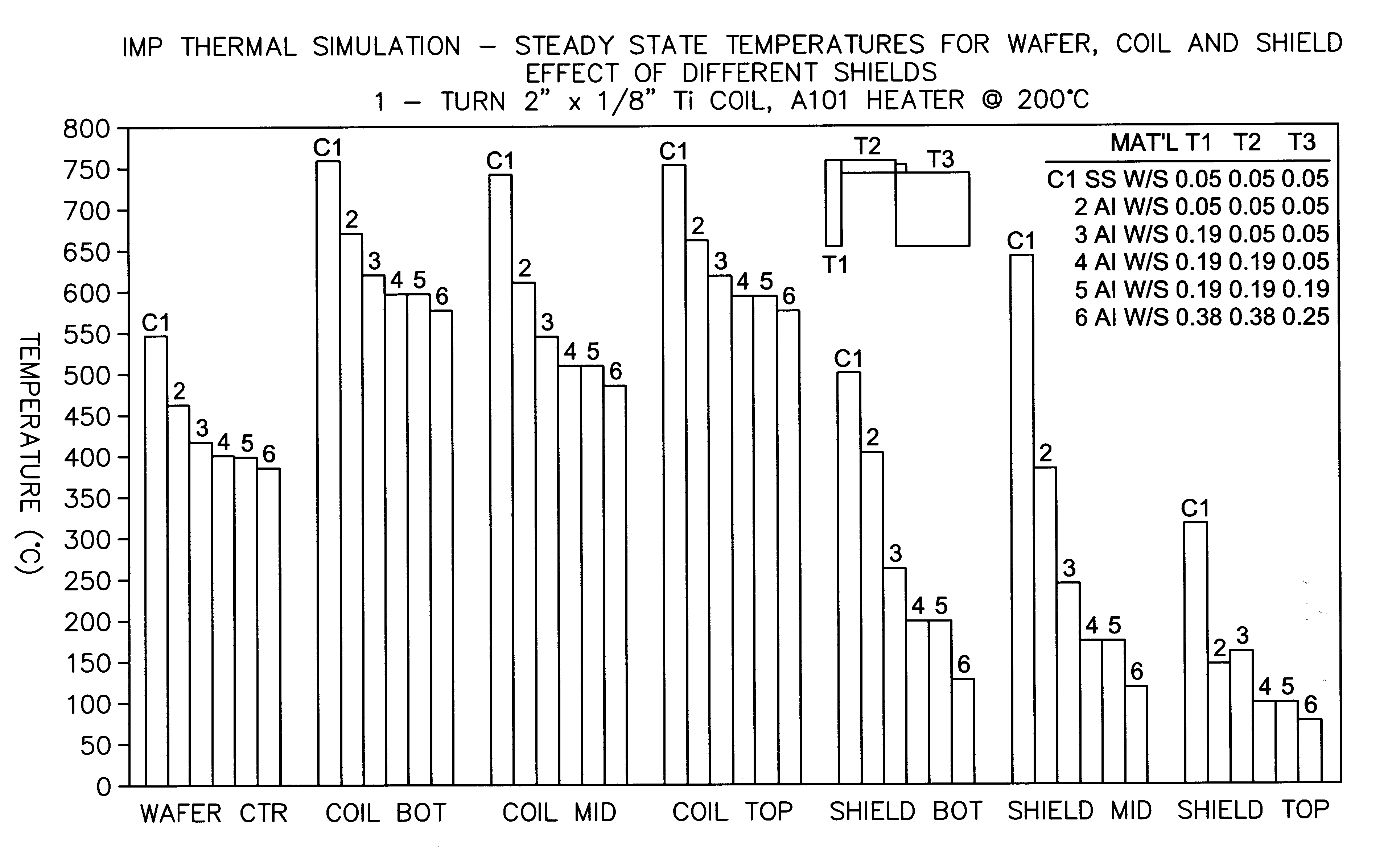
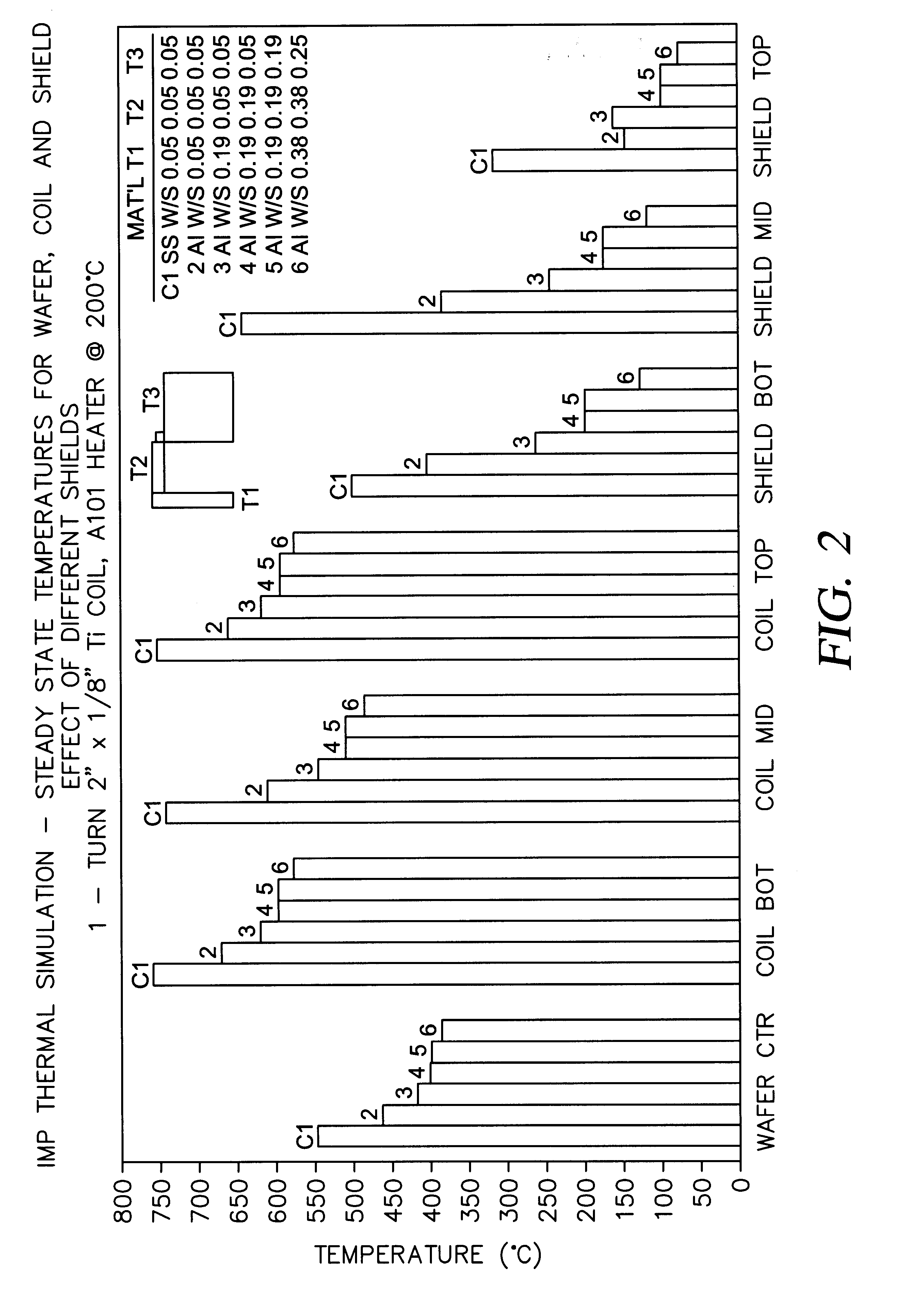
of the present invention was simulated under wafer processing conditions and compared to a stainless steel shield Example C1. During wafer processing, the wafer was heated to 200.degree. C. Each shield was supported by connectors which provides some convection of heat to the shield. Temperatures within the vacuum chamber were recorded at the wafer center, the shield bottom, the shield top, the shield middle, the coil bottom, the coil top, and the coil bottom. Thickness of the shields are shown in FIG. 2 along with the temperature measurements. The thicker aluminum shields 5,6 provided the lowest steady state shield temperatures.

While the foregoing is directed to the preferred embodiment of the present invention, other and further embodiments of the invention may be devised without departing from the basic scope thereof. The scope of the invention is determined by the claims which follow.


PUM

PropertyMeasurementUnit
thicknessaaaaaaaaaa
thicknessaaaaaaaaaa
thicknessaaaaaaaaaa

Abstract

An aluminum deposition shield substantially improves transfer of radiated heat from within the vacuum chamber, in comparison to a stainless steel deposition shield. The aluminum deposition shield remains cooler during wafer processing and assists in cooling the chamber components.

Description

The present invention relates to an apparatus for processing wafers in a vacuum chamber. More particularly, the invention relates to an apparatus for removal of heat from a vacuum chamber.BACKGROUND OF THE RELATED ARTConnecting a power source, such as a radio frequency ("RF") power source, to a device, such as an RF antenna coil, through the wall of a vacuum chamber typically involves providing an insulated passage through one or more deposition shields. Application of RF energy to the coil tends to generate heat within the chamber. This heat is dissipated through radiation and conduction to heat sinks typically the shield, target, etc. within the chamber. Deposition shields are typically constructed of stainless steel for strength and tend to be negatively charged or grounded during wafer processing. Furthermore, the shield accumulates heat during wafer processing and chamber cooling declines unless the additional heat is removed from the shield. There is a need, therefore, for a d...

Claims


Application Information

Patent Timeline
Patent Type & Authority Patents(United States)
IPC IPC(8): H01J37/32C23C14/00H05H1/46
CPCH01J37/32623H01J37/3441H01J37/32651
Inventor SUBRAMANI, ANANTHADAS, ASHOK K.DELAURENTIS, LEIF E.ROSENSTEIN, MICHAEL
Owner APPLIED MATERIALS INC
Learn More