Exterior wall sealing system

a sealing system and exterior wall technology, applied in heat proofing, foundation engineering, animal husbandry and other directions, can solve the problems of common gaps in the building envelop

Inactive Publication Date: 2003-07-15
CONTRERAS VICTOR +1
View PDF15 Cites 54 Cited by
  • Summary
  • Abstract
  • Description
  • Claims
  • Application Information

AI Technical Summary

Benefits of technology

It also provides such a system wherein such blocker comprises an adhesive and a thin material layer cooperating to block the passage of the vermin. And, it provides such a system wherein such foam seal comprises a round compressive seal. Also, it provides such a system wherein such foam seal further comprises a two-sided flat compressive seal; and wherein such foam seal cooperates with such adhesive and a thin material layer to block the passage of the vermin between the foundation and such screed. Further, it provides such a system wherein such two-sided flat compressive seal comprises adhesive on at least one side. And, it provides such a system wherein such foam seal further comprises a B-cross-section configuration compressive seal comprising a first longitudinal side with a flat portion, a second longitudinal side with two convex portions, and a center concave portion, wherein such flat portion further comprises an adhesive and a removable release sheet covering such adhesive, and wherein such flat portion of such B-cross-section configuration compressive seal is adhesively attached to the back of such planar substantially vertical upper portion of such screed, whereby a caulking bead placed in such center concave portion will assist in sealing such screed when attached to the juncture between the foundation and the base plate.

Problems solved by technology

During the framing process, application of the channel, and application of the stucco, it is common to have gaps occur in the building envelope.

Method used


Image

  • Exterior wall sealing system
  • Exterior wall sealing system
  • Exterior wall sealing system

Examples


first embodiment

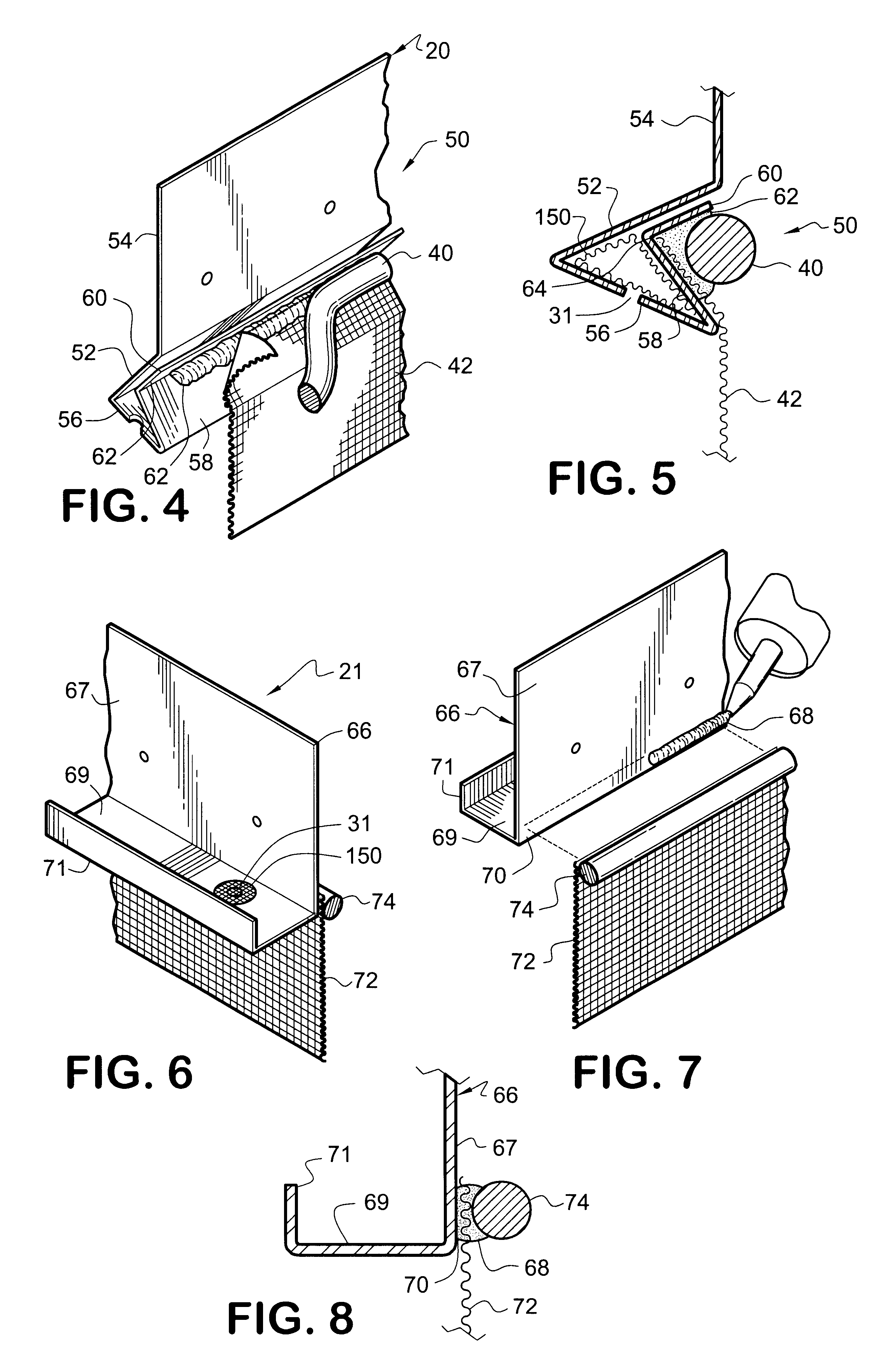
FIG. 6 is a perspective view, partially in section, of yet another embodiment 21 of the exterior wall sealing system of the present invention. In this embodiment, a prior art screed 66 is shown. Preferably, prior art screed 66 comprises an upper substantially vertical portion 67; and a lower substantially flat horizontal bottom portion 69; wherein such upper substantially vertical portion and such lower substantially flat horizontal bottom portion are substantially perpendicular to each other. Prior art screed 66 may also include a vertical return portion 71. FIG. 7 is a perspective view, partially in section, of the method of assembling the embodiment of FIG. 6. FIG. 8 is an enlarged partial side view, in section, of the embodiment of FIGS. 6 and 7. The illustrated embodiment is preferably designed to be attached to such prior art screeds such that the exterior wall sealing system may be utilized on such screeds. Preferably, in this embodiment, adhesive caulk 68 is applied along th...

embodiment 100

FIG. 9 is a perspective view of a first step in making yet another preferred embodiment 100 of the exterior wall sealing system of the present invention. FIG. 10 is a perspective view of the embodiment of FIG. 9 illustrating further steps in the making of the embodiment of the exterior wall sealing system 18 of the present invention. FIG. 11 is a perspective view, partially in section, of the embodiment of FIG. 10 illustrating additional steps in the application to the structure of the embodiment of FIG. 9 of the exterior wall sealing system of the present invention. FIG. 12 is an enlarged partial side view, in section, of the embodiment of FIG. 10.

This third illustrated embodiment 100 is preferably designed such that the exterior wall sealing system may be utilized on existing screeds which have already been installed. Preferably, in this embodiment, foam seal element 80 comprises a double-sided-adhesive-coated compressive type seal, which is preferably flat, as shown (this arrange...

embodiment 111

FIG. 13 is a perspective view of a first step in making yet another preferred embodiment 111 of the exterior wall sealing system of the present invention. FIG. 14 is a perspective view, partially in section, of the embodiment of FIG. 13 illustrating further steps in the making of the embodiment of FIG. 13. FIG. 15 is an enlarged side view, in section, of the embodiment of FIG. 14. Preferably, this embodiment is designed such that the exterior wall sealing system may be utilized on screeds which may not require or be able to utilize, under particular circumstances, the fiberglass netting portion of the above described embodiments. Such installations may include, for example, foundations where a perimeter sidewalk is poured right up to the foundation. Preferably, in this embodiment, foam seal element 102, a compressive type seal, is applied to the lower back portion 104 of the screed 106. Preferably, foam seal element 102 comprises a B-cross-section configuration structure, as shown, ...


PUM

PropertyMeasurementUnit
compressiveaaaaaaaaaa
flexibleaaaaaaaaaa
perimeteraaaaaaaaaa

Abstract

A system for sealing the gaps that occur along the perimeter of a building envelope, particularly along with installation of an exterior finish system channel, or screed, as occurs in the installation and application of stucco. It is common to have gaps occur between the channel, base plate, and foundation of the building envelope. The system utilizes a foam sealing element in combination with the channel, caulking, a fiberglass netting that is installed along the bottom of the channel and the face of the foundation, and, an adhesive sealant that seals and adheres the fiberglass netting to the foundation. The system includes several embodiments for use in either new construction or as an aftermarket product.

Description

This invention relates to providing a system for sealing the gaps that occur along the perimeter of a building envelope. Typically, constructing walls of buildings may be accomplished by a variety of methods. One such method is to utilize wood or steel framing members to create a framed wall. These framed walls typically consist of framing members with a horizontal top and bottom piece (typically referred to as a top plate and a bottom plate or base plate) and vertical members attached from top plate to bottom plate and placed at intervals of about 16 inches or about 24 inches (typically referred to as studs). The bottom plate is typically attached to a cement or wood foundation. The combination of the dependent walls attached together and the roof create a firm structure. Depending on the type of building and local code, the exterior of the framed walls may be sheathed. The sheathing may be plywood, brick, stucco, vinyl, wood or other exterior finish system. Sheets of gypsum board ...

Claims


Application Information

Patent Timeline
Patent Type & Authority Patents(United States)
IPC IPC(8): E04B1/76E04F13/08E04F13/02E04F13/06
CPCE04B1/762E04B1/765E04F13/06E04F13/0889E04F13/068E04F2013/066E04F2013/065
Inventor CONTRERAS, VICTORCONTRERAS, SANDRA
Owner CONTRERAS VICTOR
Why Eureka
Try Eureka