Rolled paper dispensing system

a dispensing system and roll paper technology, applied in the field of roll paper dispensing system, can solve the problems that no prior art device singly or even in combination provides for all, and achieve the effects of convenient releasability of latches, convenient positioning, and useful braking

Inactive Publication Date: 2003-07-15
FUJIWARA JAYME ATSUKO
View PDF26 Cites 32 Cited by
  • Summary
  • Abstract
  • Description
  • Claims
  • Application Information

AI Technical Summary

Benefits of technology

e) Operation requires too much time and skill.
The rolled paper dispensing system of this invention comprises a cradle in a housing enclosure with easily releasable latch lock. The semi-circular cradle provides a stable storage means that can be located easily. It also gives useful braking from the friction with the rotating roll. The hinge and latch feature make it easy to deploy and retract it to the loading mode or the dispensing mode. The enclosure housing can be mounted on a vertical and horizontal surface. If mounted on a vertical surface, the top makes a handy shelf. The cutting edge guide, combined with the braking drag simplifies tearing rolled paper sheets from the dispenser. The housing enclosure prevents accidental dislodgement and contamination. Prior art dispensers have exposed rolled material. This constitutes a critical difference for some users.
a) The user is not required to disassemble and assemble hardware to unload and load the rolled material.
c) The dispenser cabinet completely encloses the rolled material which prevents accidental dislodging and contamination. Finally, with the range of plastic and other materials available to make the dispenser, it can be made attractive, durable, trouble free and affordable.
1. It is an objective of this invention to provide methods, devices and system for quickly, conveniently dispensing all types of rolled sheet material.
2. Another objective of this invention is to provide aesthetic and elegant design that integrates harmoniously with the environment.

Problems solved by technology

Unfortunately none of the prior art devices singly or even in combination provide for all of the objectives as established by the inventor for this system as enumerated below.

Method used


Image

  • Rolled paper dispensing system
  • Rolled paper dispensing system
  • Rolled paper dispensing system

Examples


Embodiment Construction

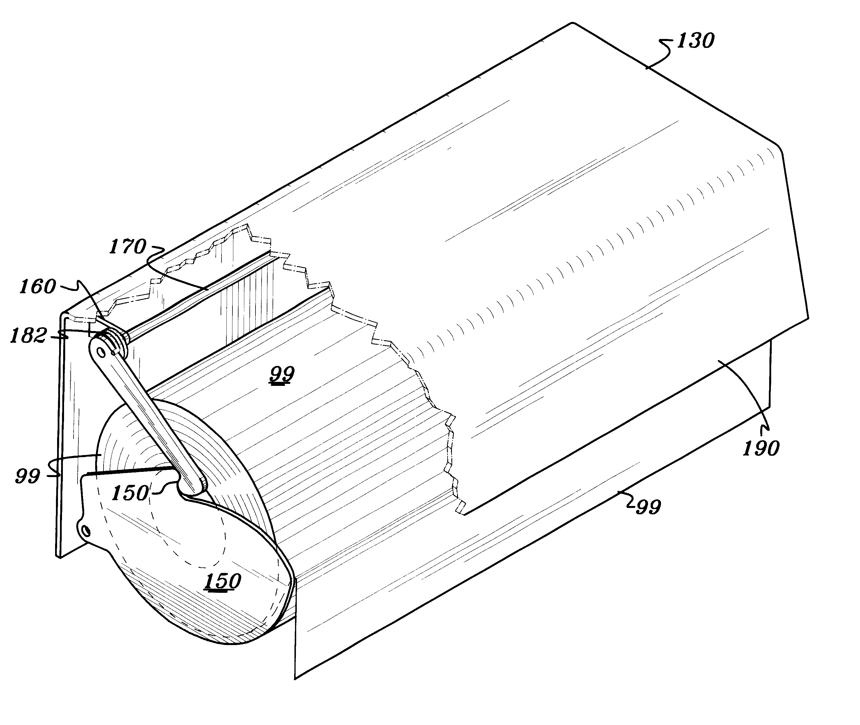
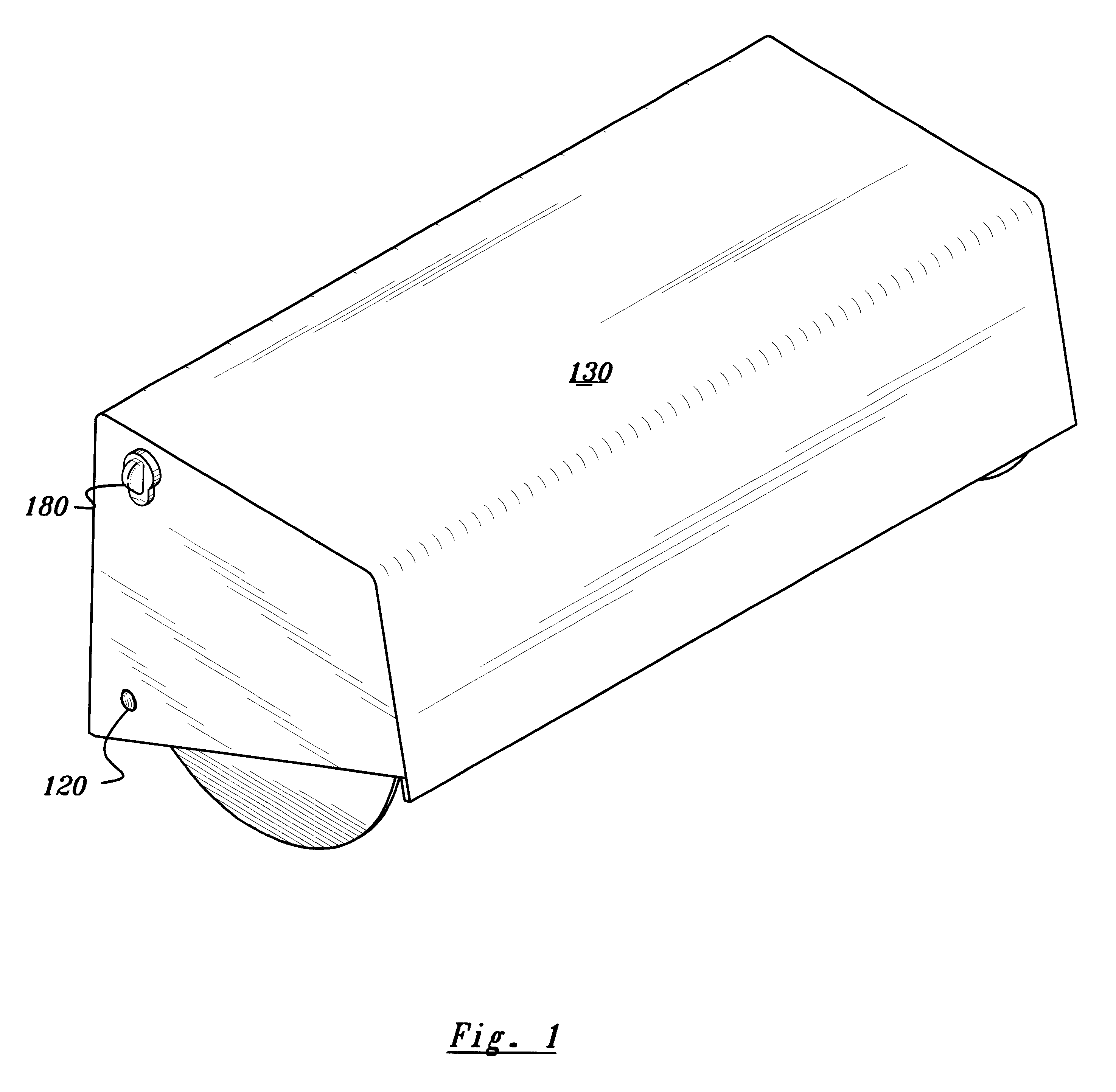
The rolled paper dispensing system of this invention as shown in the drawings wherein like numerals represent like parts throughout the several views, there is generally disclosed in FIG. 1 is a 3D isometric perspective view of the rolled paper dispensing system of this invention complete with housing 130, latch lock 150 and latch release knob 180

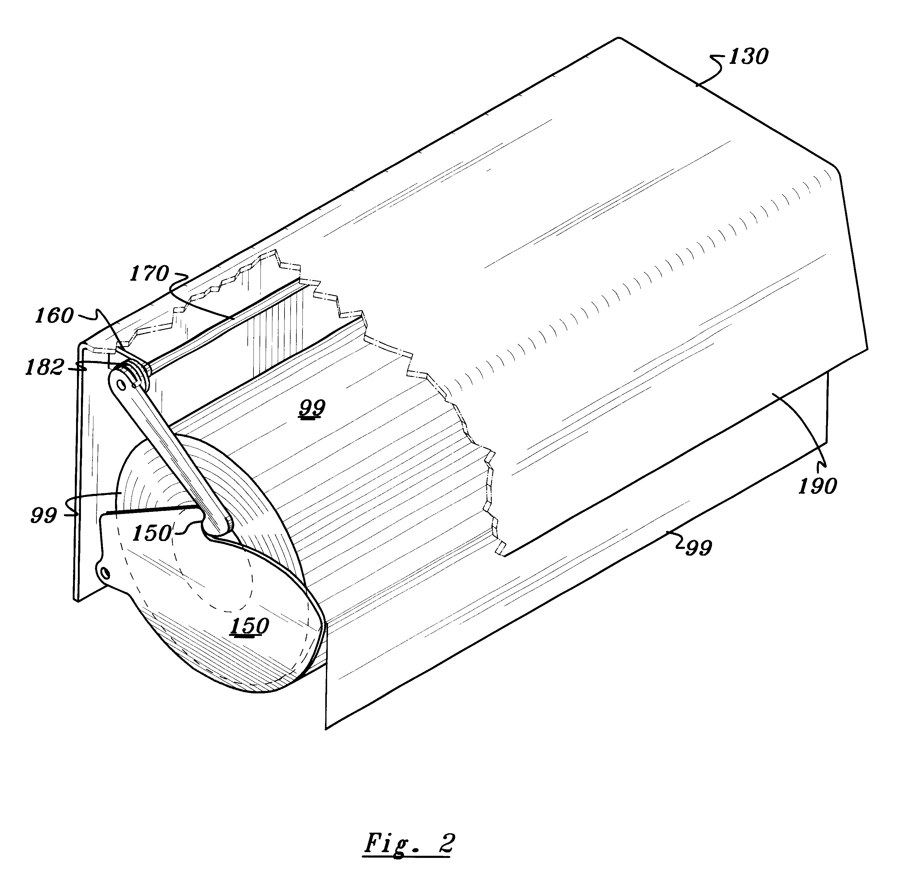
The rolled paper dispensing system of this invention compares a cradle in a housing enclosure with easily releasable latch lock. The semi-circular cradle provides a stable storage means that can be located easily. It also gives useful braking from the friction with the rotating roll. The hinge and latch feature make it easy to deploy and retract it to the loading mode or the dispensing mode. The enclosure housing can be mounted on a vertical and horizontal surface. If mounted on a vertical surface, the top would make a handy shelf. The cutting edge guide, combined with the braking drag simplifies tearing rolled paper sheets from the dispens...


PUM


Abstract

The perforated roll dispensing system comprises a hinged cradle within a housing enclosure with easily releasable latch lock. The semi-circular cradle trough provides a stable storage means for perforated roll products. The textured surface of the trough gives useful braking from the friction with the rotating roll for controlled metering and provides adequate resistance to tear and extract unity of the sheet material from the dispenser without unraveling. The hinge and latch feature make it easy to deploy and retract the cradle trough to the loading mode or the dispensing mode. The right angled top enclosure and back panel of the housing can be mounted on a vertical and horizontal surface.

Description

This invention relates generally to the art of dispensing sheet material. More particularly it relates to method, devices and system for dispensing rolled paper products such as paper towels, toilet paper etc.The ProblemThe problem with prior art sheet material dispensing devices and systems is that they are not suitable for hassle free, low cost dispensing of rolled paper.a) Not hassle freeb) Not integrated into a slim aesthetic portable design.c) Not cost effective.d) Limited functionality.e) Operation requires too much time and skill.f) Complex with too many moving parts.g) Do not control precision in dispensingThey either unroll too easily (free spool types) or have difficulties from inadequate restraining and braking force or too much of it.It is too loose, it can come free and unless you have hand ready to catch it, user would be chasing it on the floor or counter. It requires both hands to tear the sheet material from the roll. It takes a reasonably dexterous and alert person...

Claims


Application Information

Patent Timeline
Patent Type & Authority Patents(United States)
IPC IPC(8): A47K10/24A47K10/38B65H35/00
CPCA47K10/38B65H35/0006A47K2010/3863Y10T225/282Y10T225/20Y10T225/246Y10T225/254Y10T225/238
Inventor FUJIWARA, LESLIE H.
Owner FUJIWARA JAYME ATSUKO
Why Eureka
Try Eureka