
Apparatus and method for monitoring and controlling laboratory information and/or instruments

Inactive Publication Date: 2003-07-15
THERMO BIO ANALYSIS
View PDF1 Cites 72 Cited by
  • Summary
  • Abstract
  • Description
  • Claims
  • Application Information

AI Technical Summary

Problems solved by technology

Such customisation may require many weeks of expensive coding, with or without the aid of regulated business models, in order that the LIMS system can operate according to a particular laboratory's exact requirements.
Should these requirements change at a future date, for example with the introduction of new statutory requirements, further expensive coding will be necessary.
The amount of effort required to customise the base software can often be the major financial and time cost of a LIMS installation.
Such customisation is not only complex and expensive but it can lead to problems for the customer in terms of upgrading and validating their LIMS.
However, to write separate bespoke programs to address the many different test procedures in a large laboratory (as frequently occurred in the prior art) may require several million lines of code.

Method used


Image

  • Apparatus and method for monitoring and controlling laboratory information and/or instruments
  • Apparatus and method for monitoring and controlling laboratory information and/or instruments
  • Apparatus and method for monitoring and controlling laboratory information and/or instruments

Examples


Embodiment Construction

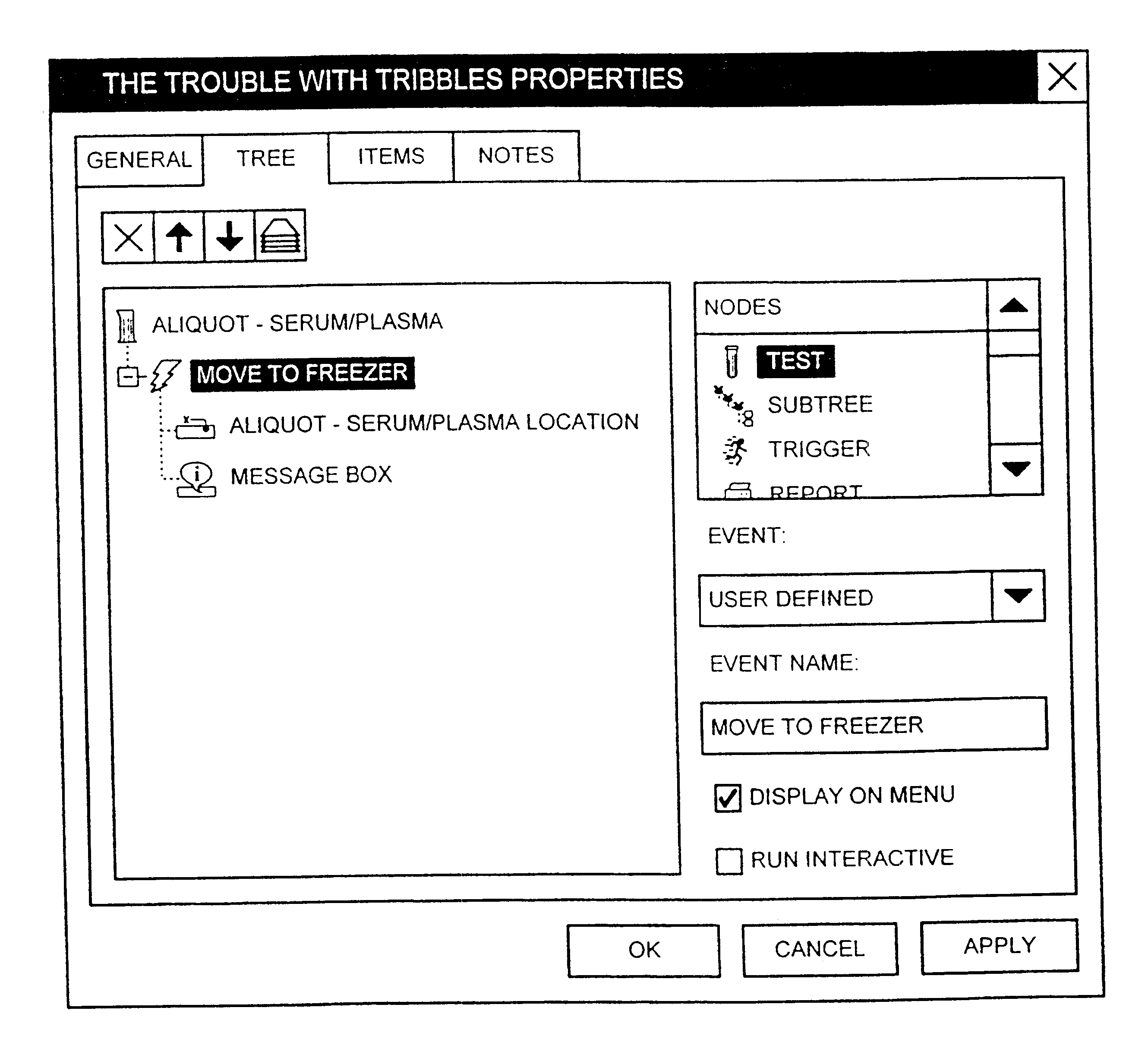
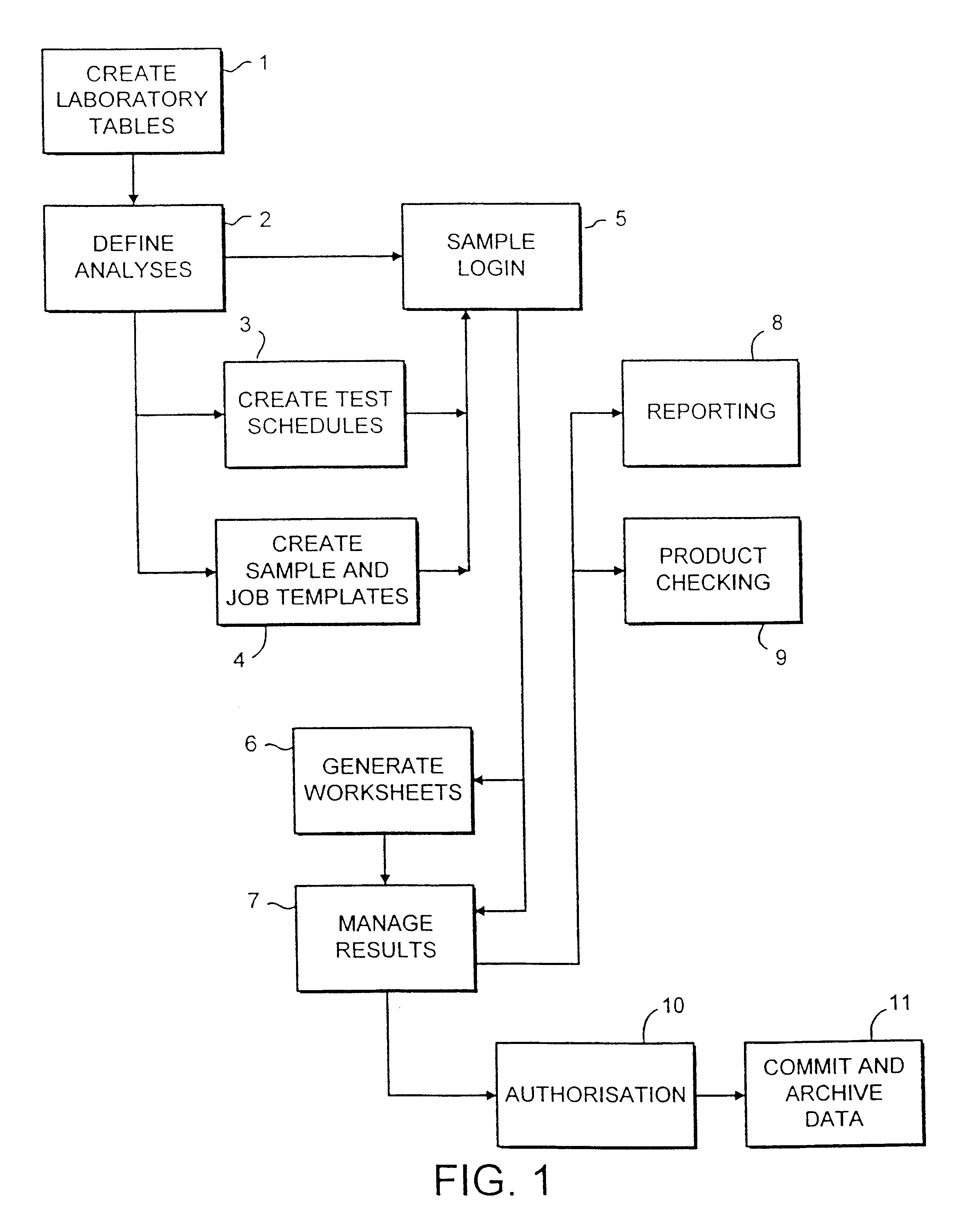
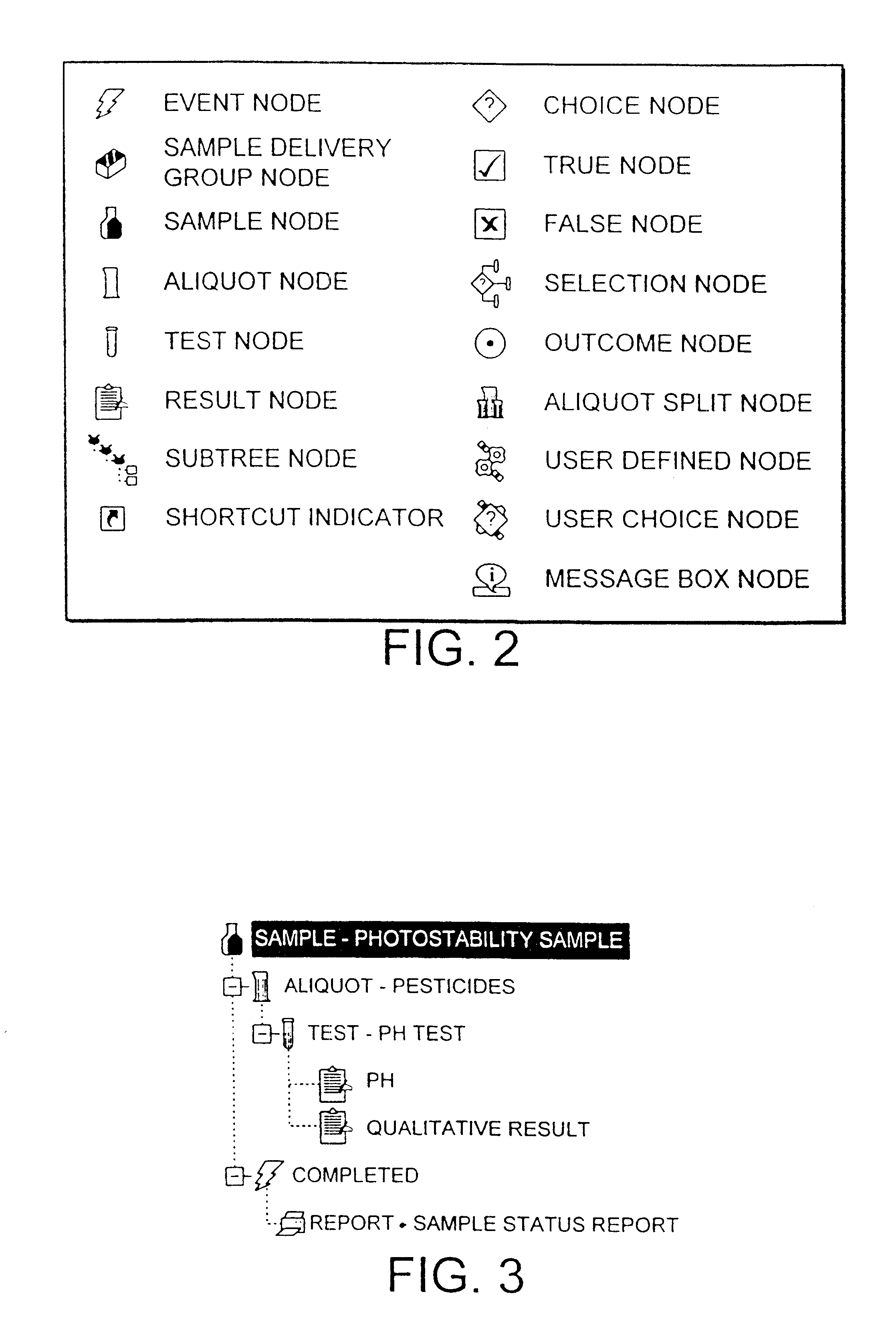
The operation of the invention relies on the concept of the workflow. A workflow in this context is a model of the laboratory process which defines the events be carried out on a sample or samples. The workflow may include the steps of defining a sample and / or sample group, splitting off and defining aliquots of samples, specifying decisions to be taken, tests to be applied and reports to be printed. The user can build a macroscopic workflow using graphical tools which correspond to workflow nodes. In this way, often complex laboratory processes can be modelled using a structured task list made up of a series of workflow nodes selected by the user. The workflow can be structured to incorporate specific event nodes which allow status changes or report processing, for example, to be triggered as a response to the outcome of a particular test. In summary, a workflow defines the business rules for events to be carried out on a sample. As the structure of a workflow is hierarchical, it i...


PUM


Abstract

A system and method for handling laboratory information includes a graphical user interface with a plurality of windows. A palette of icons is provided in a first one of the windows, each icon representing a predetermined task to be executed by a processor in communication with the graphical user interface. The processor is also in communication with a database containing static laboratory data (such as the type of sample to be analysed) as well as dynamic laboratory data (such as the name of the specific sample to be tested and the results of that test). A user can select icons from the first window and "drag and drop" them into a second window. A sequence of tasks may thus be built up, in the form of a tree structure, and when run the processor executes the sequence of tasks in turn by reference to the static and dynamic laboratory data.

Description

This application is a 35 U.S.C. .sctn.371 filing of International Patent Application No. PCT / GB99 / 01569, filed May 17, 1999. This application claims priority benefit of Great Britain Patent Application No. 9810574.5, filed May 18, 1998.This invention relates to the field of monitoring and controlling laboratory information and / or laboratory instruments.BACKGROUND TO THE INVENTIONThe word laboratory may be taken to encompass many different types of establishment, from a single room containing one or two scientific instruments to a building housing hundreds of scientists and pieces of equipment; from a place of academic research to the process control room of a brewery, food manufacturing plant, oil refinery, chemical or pharmaceutical facility etc. What most laboratories have in common is their function of performing scientific tests or experiments and their product, laboratory information. In a modern laboratory, there may be hundreds of samples, in respect of each of which hundreds...

Claims


Application Information

Patent Timeline
IPC IPC(8): G06F9/44
CPCG06F8/34Y10S707/99944Y10S707/99947
Inventor PEDEN, JOSEPH MARTINSKINNER, MORGAN NICHOLASJONES, ROBIN DYLANDAVIS, ANDREW MARTINHOLT, PHILIP IANTAYLOR, GRAHAM STUART
Owner THERMO BIO ANALYSIS
Learn More