Thermal protector

a technology of thermal protection and shielding layer, which is applied in the direction of thermal switch details, contact, basic electric elements, etc., can solve the problems of inability to protect the shielding layer, etc., to achieve high hermetically sealing ability and simple and low-cost construction

Inactive Publication Date: 2003-07-22
UCHIYA THERMOSTAT
View PDF9 Cites 12 Cited by
  • Summary
  • Abstract
  • Description
  • Claims
  • Application Information

AI Technical Summary

Benefits of technology

The present invention has been made in view of the above situation, and accordingly an object thereof is to provide a thermal protector that can provide high hermetically sealing ability with a simple and low-cost construction and also can be of a small and thin shape.
According to the present invention, there can be provided a thermal protector that can keep the switching mechanism section in a hermetically sealed state with a simple and low-cost construction.
The end face of the peripheral wall of the case is preferably formed so as to be flush to increase the sealing ability of the cover member and further decrease the thickness of the thermal protector.
This thermal protector can provide the same effect as that of the thermal protector having the bottomed case.

Problems solved by technology

Further, when insulating vanish is used in an assembling process for equipment to which the thermal protector is applied, the insulating vanish sometimes intrude into the switching mechanism section.
The aforementioned entrance of water, electrolyte, vanish, and the like into the switch mechanism section may impair the function of the switching mechanism section.
Furthermore, for a lithium ion battery in which the secondary battery of the battery pack uses flammable electrolyte, leaking electrolyte may be ignited by an arc generated at a contact of the switch mechanism.
However, any of the aforementioned measures requires much time and labor in fabrication.
Also, the measure in which the opening is sealed with a packing requires much time and labor to mount packings one by one.
Also, any of the aforementioned measures has a problem in that it is difficult to make the whole shape of thermal protector small and thin by using a thin case because the case must have strength.
However, if the thickness of the cover is decreased to provide a thin shape, the cover cannot withstand vibration energy needed for the ultrasonic welding, and therefore may be damaged.

Method used


Image

  • Thermal protector
  • Thermal protector
  • Thermal protector

Examples


Embodiment Construction

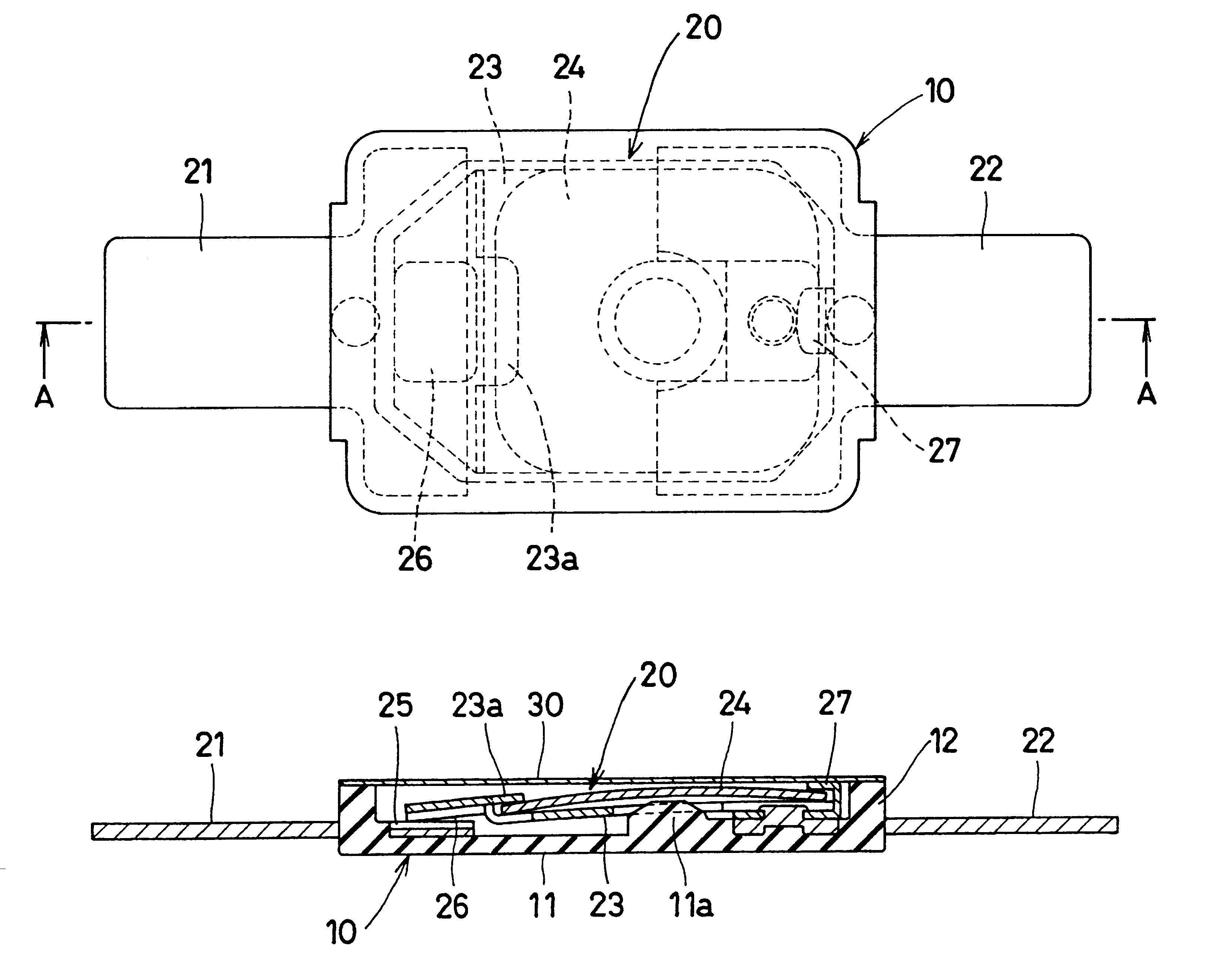
The cover member 30 of construction example 1 has a construction such that a film consisting of a thermosetting resin or paper having electric insulating properties is used as a base material, and one surface of the base material is coated with a thermoplastic resin, thereby forming a adhesive layer.

As the aforementioned thermosetting resin, polyimide resin or the like is used, and as the paper, heat resisting paper such as aramid paper is used. As the thermoplastic resin, polyamide, polyolefin, EVA, polyester, or the like is used.

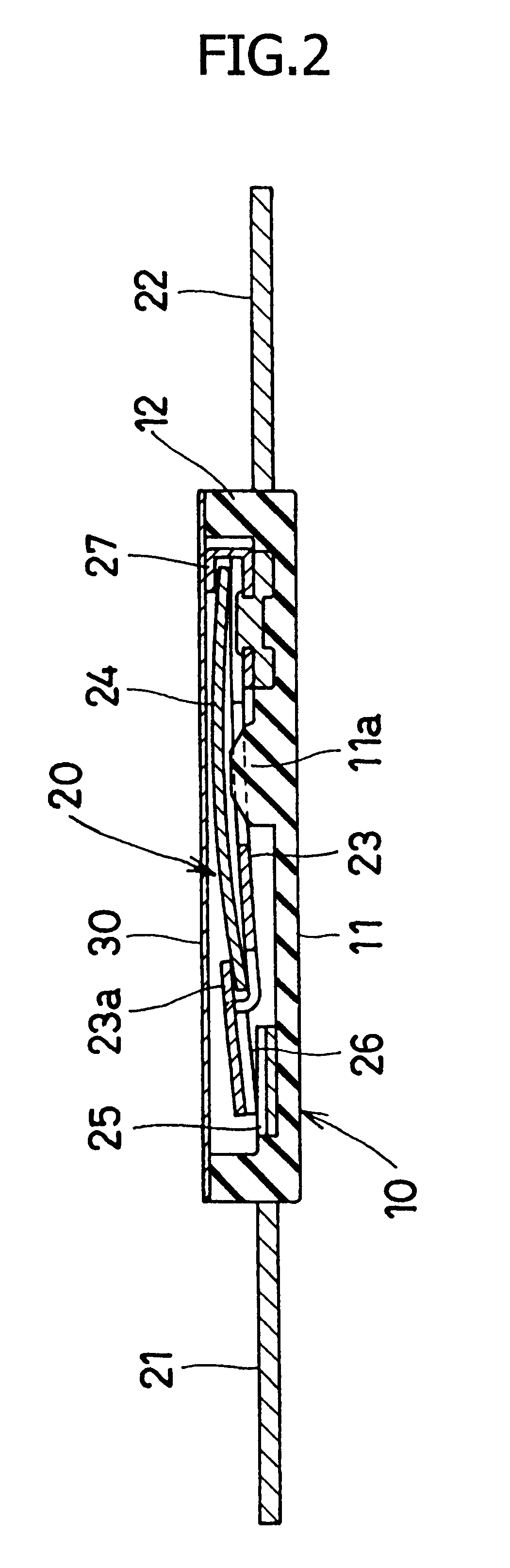
This cover member 30 is disposed in such a manner that the adhesive layer abuts against the upper end face of the peripheral wall 12, and is adhesively fixed to the upper end face of the peripheral wall 12 by melting the adhesive layer with heat.

(2) Construction Example 2

The cover member 30 of construction example 2 has a construction such that a film consisting of a thermosetting resin or paper having electric insulating properties is used as a base mater...


PUM


Abstract

A thermal projector includes a switching mechanism section having a fixed contact, a movable contact disposed so as to face the fixed contact. There are first and second external connection terminals projecting sideward and connected electrically to the fixed contact and movable contact, respectively. The switching mechanism section is constructed so that the movable contact is displaced by a deforming operation of a thermally-actuated element so as to be separated from and brought into contact with the fixed contact. A resin bottomed case having a peripheral wall is located around the switching mechanism section in a manner so that the first and second external connection terminals penetrate the peripheral wall, and the penetrating portions are adhesively sealed by molding the peripheral wall integrally with the connection terminals. There is a film formed member of an electric insulating material. The cover member is adhesively fixed to the upper end face of the peripheral wall of the case so as to seal the upper opening of the case.

Description

FIELD OF THE INVENTION AND RELATED ART STATEMENTThe present invention relates to a thermal protector used to prevent danger such as fire caused by an excessive rise in temperature of electrical equipment.For the thermal protector of this type, water or the like sometimes intrudes into a switching mechanism section thereof depending on the operating environment of equipment to which the thermal protector is applied. Also, when the thermal protector of this type is incorporated in a small-size battery pack, electrolyte leaking from a secondary battery in the battery pack sometimes intrudes into the switching mechanism section. Further, when insulating vanish is used in an assembling process for equipment to which the thermal protector is applied, the insulating vanish sometimes intrude into the switching mechanism section.The aforementioned entrance of water, electrolyte, vanish, and the like into the switch mechanism section may impair the function of the switching mechanism section....

Claims


Application Information

Patent Timeline
Patent Type & Authority Patents(United States)
IPC IPC(8): H01H37/00H01H37/54H01H37/32H01H37/04H01H11/00H01H37/52H01H37/76
CPCH01H37/5427H01H37/323H01H2001/506H01H2037/5481
Inventor TAKEDA, HIDEAKI
Owner UCHIYA THERMOSTAT
Why Eureka
Try Eureka