Electronic animal trap

a technology electronic components, applied in the field of electronic animal traps, can solve the problems of limited success in efforts, tendency of captured rodents to crawl under, nest,

Inactive Publication Date: 2003-08-26
WOODSTREAM CORP
View PDF26 Cites 53 Cited by
  • Summary
  • Abstract
  • Description
  • Claims
  • Application Information

AI Technical Summary

Benefits of technology

It is another object of the invention to provide an electric or electronic animal trap including a housing with a bottom wall, upstanding peripheral walls, and a cover, together defining an enclosure for holding at least one targeted animal with contacts on portions of the peripheral walls and cover adapted to open or "break" the circuitry when the cover is lifted thereby avoiding accidental injury to a person contacting the electrodes when accessing the enclosure to add bait or to remove electrocuted animals.
It is a further object of the invention to provide, the door member being biased toward its lowered position, the weight of the door member on the first end portion of the floor member when the door member is in its lowered position maintaining the floor member in its first position, and the weight of an animal on the floor member tilting the floor member to its second position when the animal passes from the entrances opening beyond the pivot element to thereby lift the door member to its raised position.
It is a further object of the invention to provide for the bottom electrical connection member to receive the electricity from the circuit member and connecting to the bottom plate to provide electricity to the bottom plate and the weight of the animal on the floor member tilting the floor member to its second position when the animal passes from the entrance opening beyond the pivot element to thereby lift the door member to its raised position to eliminate an exit of the animal from the trap.

Problems solved by technology

When the rodent exits the passageway into the enclosure the door falls by gravity on the entrance end of the tilting floor to reset the trap and the raised end of the tilting floor limits the ability of a captured rodent to return to the passageway.
Attempts have been made to limit access to the tilting floor and the door by incorporation of various flanges or lips on the trap assembly walls or roof, but such efforts have had limited success.
Another problem associated with animal traps is the tendency of a captured rodent to crawl under, or nest in the space between the bottom wall of the trap housing and the undersurface of the raised end of the tilting floor when the trap assembly has been reset.
These traps, so far, have very complicated structures which are costly to manufacture.
Additionally, these traps are not conveniently employed without disruption of the animal's environment nor are they able to control the voltage to the trap.
Some are designed, to provide continuous power which is not cost effective and others can not keep the animal in the trap, because the animal can grasp the top of a side edge of the trap door and scratch or chew its way out.
The problem with this type of device is that voltage only occurs when the pest makes contact with the flexible plate.
The trap door is non-existing and the pest can readily escape, thus defeating the purpose of the trap.
A problem with this device is that a separate ground stake is necessary.
It is costly and cumbersome.
If the user forgets or misplaces the separate ground stake, the device does not work correctly and thus will be useless.
While the noted prior art patents show electronic members in a trap, none of the patents disclose a combination of an electronic circuit fixed in a trap with a teeter-totter mechanism to securely close the trap door, and thus readily exterminating the pest by electrocution.
Previous electric mouse killing traps had deficiencies regarding the safety features and the reliability of the device.
Therefore, it will complete the circuit resulting in the death of the animal.

Method used


Image

  • Electronic animal trap
  • Electronic animal trap
  • Electronic animal trap

Examples


Embodiment Construction

Although only one preferred embodiment of the invention is explained in detail, it is to be understood that other embodiments are possible. Accordingly, it is not intended that the invention is to be limited in its scope to the details of construction and arrangement of components set forth in the following description or illustrated in the drawings. The invention is capable of other embodiments and of being practiced or carried out in various ways. Also, in describing the preferred embodiment, specific terminology will be resorted to for the sake of clarity. It is to be understood that each specific term includes all technical equivalents which operate in a similar manner to accomplish a similar purpose.

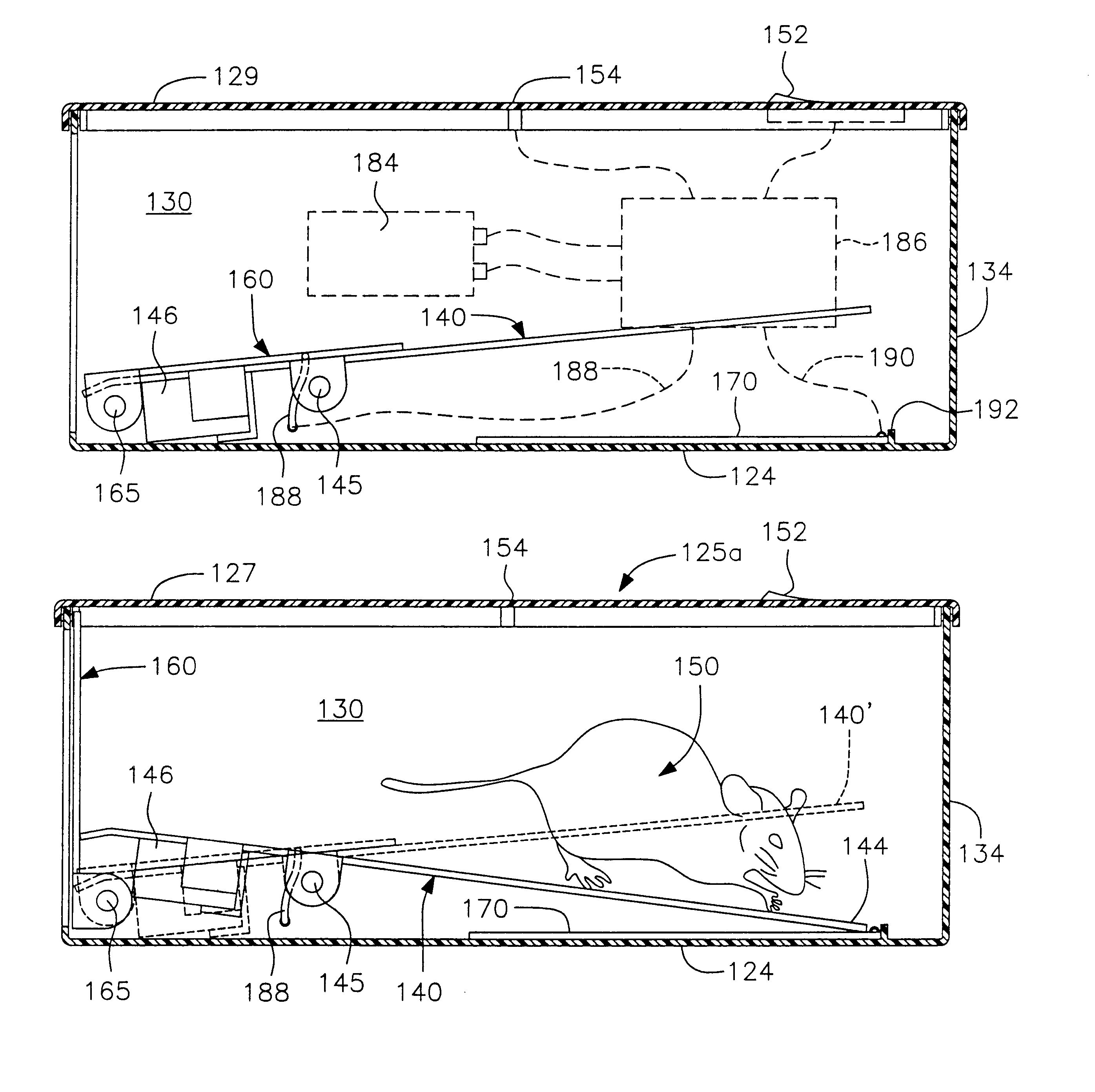
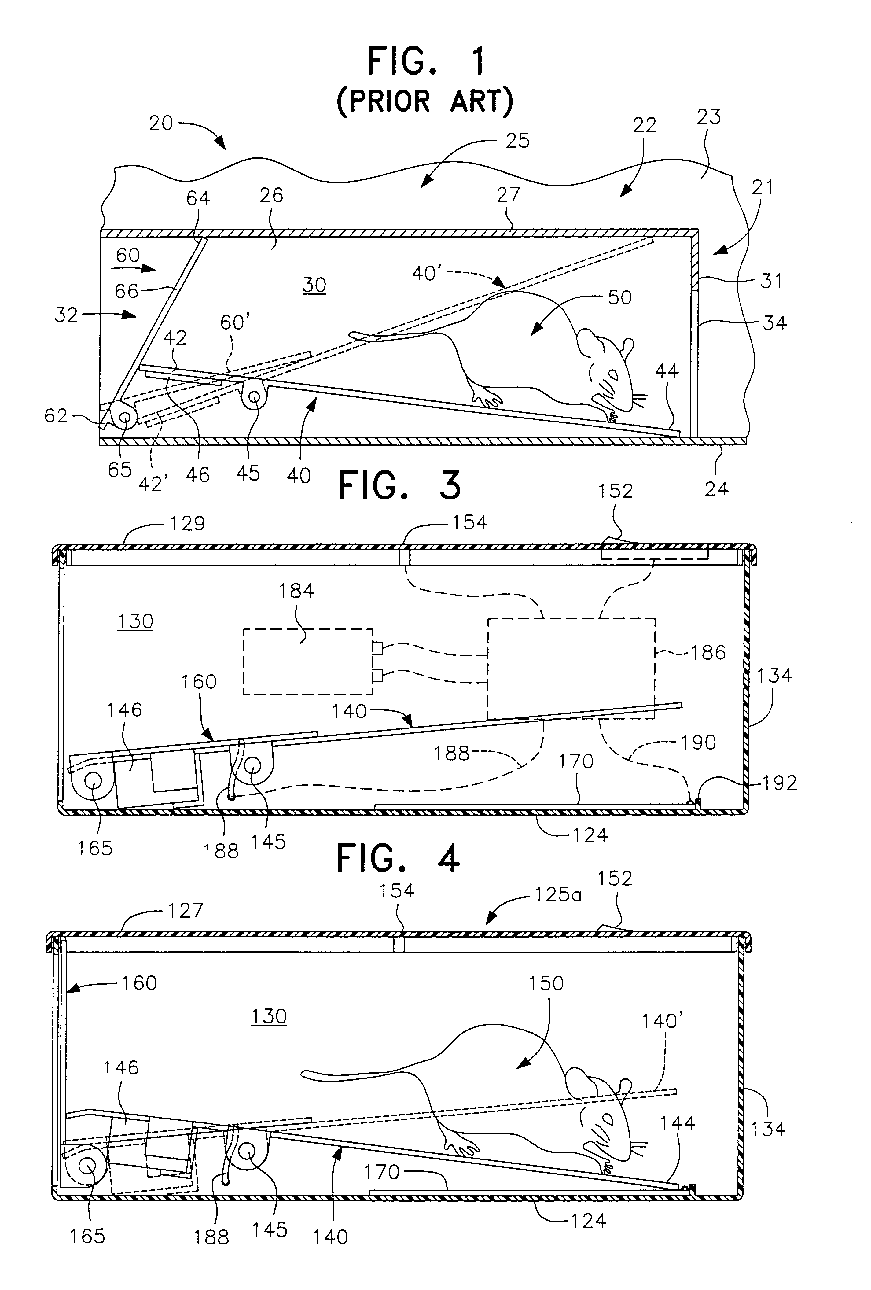
Referring to FIG. 1, portions of an animal trap without an electronic circuit of the type seen in the aforementioned application Ser. No. 09 / 729,832 is designated generally by the reference numeral 20 with an inclined plane trap assembly designated generally by the reference numeral...


PUM


Abstract

An electronic animal trap incorporating an inclined plane trap assembly is capable to preclude an animal on the tilting floor member of the trap assembly from engaging the top and / or side edges of the door member of the trap assembly in an attempt to escape from the trap by pulling the door member down to thereby unblock access to the entrance opening. An electronic circuit is connected to a bottom plate so that when animal's weight causes the inclined ramp to lower and contact the bottom plate the circuit is completed and the animal receives a charge of sufficient power to cause electrocution. A plastic version of the electronic animal trap assembly enables many of the structural elements to be economically manufactured and easily assembled.

Description

1. Field of the InventionThe invention relates electric or electronic animal traps, and relates more particularly to an animal trap of the inclined plane type adapted to catch and electrocute a targeted animal.Although the concepts of the instant invention are equally applicable to traps for animals of any size, devices of this type are primarily utilized in connection with the trapping of rodents such as mice and rats and, therefore, further discussion herein will be primarily directed to this application.2. The Prior ArtInclined plane animal traps have been available for over one hundred years. The commercial embodiments of such traps currently available commonly comprise a housing defining an enlarged enclosure with one, or perhaps two, inclined plane trap assemblies communicating the interior of the enclosure with the exterior of the housing via an elongated passageway. An inclined plane tilting floor member is positioned in the passageway of each trap assembly and is adapted to...

Claims


Application Information

Patent Timeline
Patent Type & Authority Patents(United States)
IPC IPC(8): A01M23/00A01M23/04A01M23/38
CPCA01M23/04A01M23/38
Inventor SWIFT, DAVID W.RICH, CHRISTOPHER T.
Owner WOODSTREAM CORP
Why Eureka
Try Eureka