Exhaust control valve

a technology of exhaust control valve and valve body, which is applied in the direction of valve operating means/release devices, combustion air/fuel air treatment, machines/engines, etc., can solve the problems of high construction cost, high cost of seal member(s), and difficulty in reducing construction costs

Inactive Publication Date: 2003-08-26
HONDA MOTOR CO LTD
View PDF19 Cites 25 Cited by
  • Summary
  • Abstract
  • Description
  • Claims
  • Application Information

AI Technical Summary

Benefits of technology

An additional aspect of the present invention is to providing an inexpensive bearing bushing that provides a sealing function in an exhaust control valve.
According to a first feature of the present invention, a bearing bushing can be provided that offers a bearing function and a sealing function. Therefore, leakage of exhaust gas from the vicinity of a valve shaft can be prevented without providing a special seal member. Further, a reduction in cost can be achieved as expensive seal members are eliminated and the number of component parts is reduced.
In addition, since seal members are not used, it is possible to use a bearing bushing that is relatively long in its axial direction. Accordingly, a bearing shaft can be supported with a larger supporting surface / region, thereby ensuring a large bearing capacity. Therefore, the bearing bush can display superior durability even though it receives load directly from a driven pulley fitted to the valve shaft.
According to a second feature of the present invention, the nonmetallic bearing bushing displays a good sealing function and absorbs vibrations in the thrust direction of the valve body arising from exhaust pulsations. Accordingly, the generation of abnormal noise is further suppressed.
According to this third feature, the valve body is formed from a titanium material together with its valve shafts, whereby it is therefore possible to achieve a reduction in the weight of the valve body and, hence, the exhaust control valve. Although the titanium material of the valve body as a whole is an active metal, and has a high tendency toward seizure, the adoption of the bearing bushing formed from a carbon material makes it possible to give achieve rotational slidability between the valve shafts and the bearing bushings even in high-temperature conditions. This, in cooperation with the reduction of weight of the valve body, makes it possible to effectively enhance the response property of the valve body to driving torque.

Problems solved by technology

However, these types of exhaust control valve suffer from the following disadvantages.
Finally, the seal member(s) are expensive, and therefore making it difficult to reduce construction costs.

Method used


Image

  • Exhaust control valve
  • Exhaust control valve
  • Exhaust control valve

Examples


Embodiment Construction

The present invention will now be described with reference to the embodiments illustrated by the accompanying drawings.

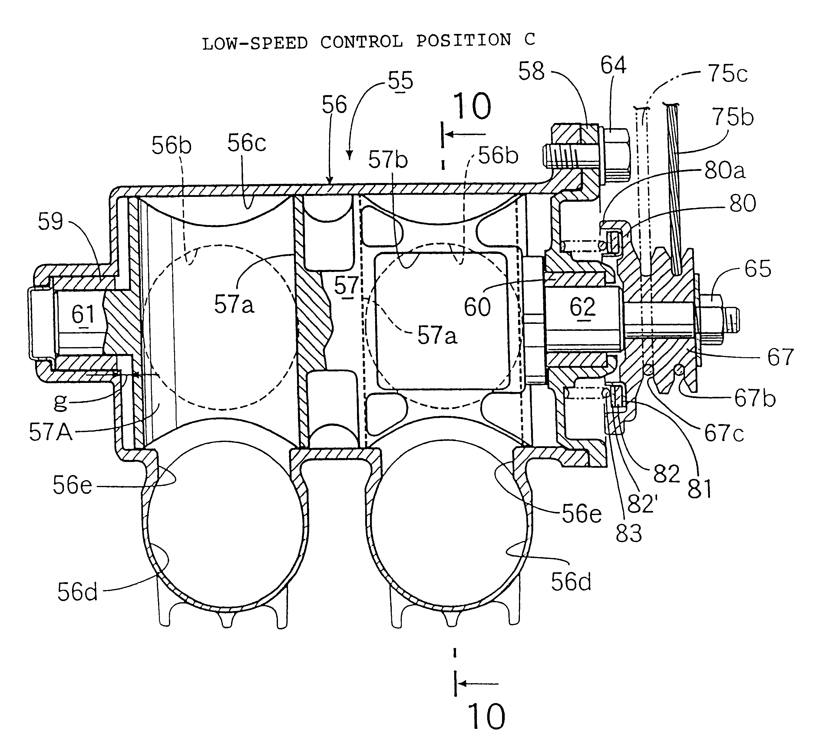
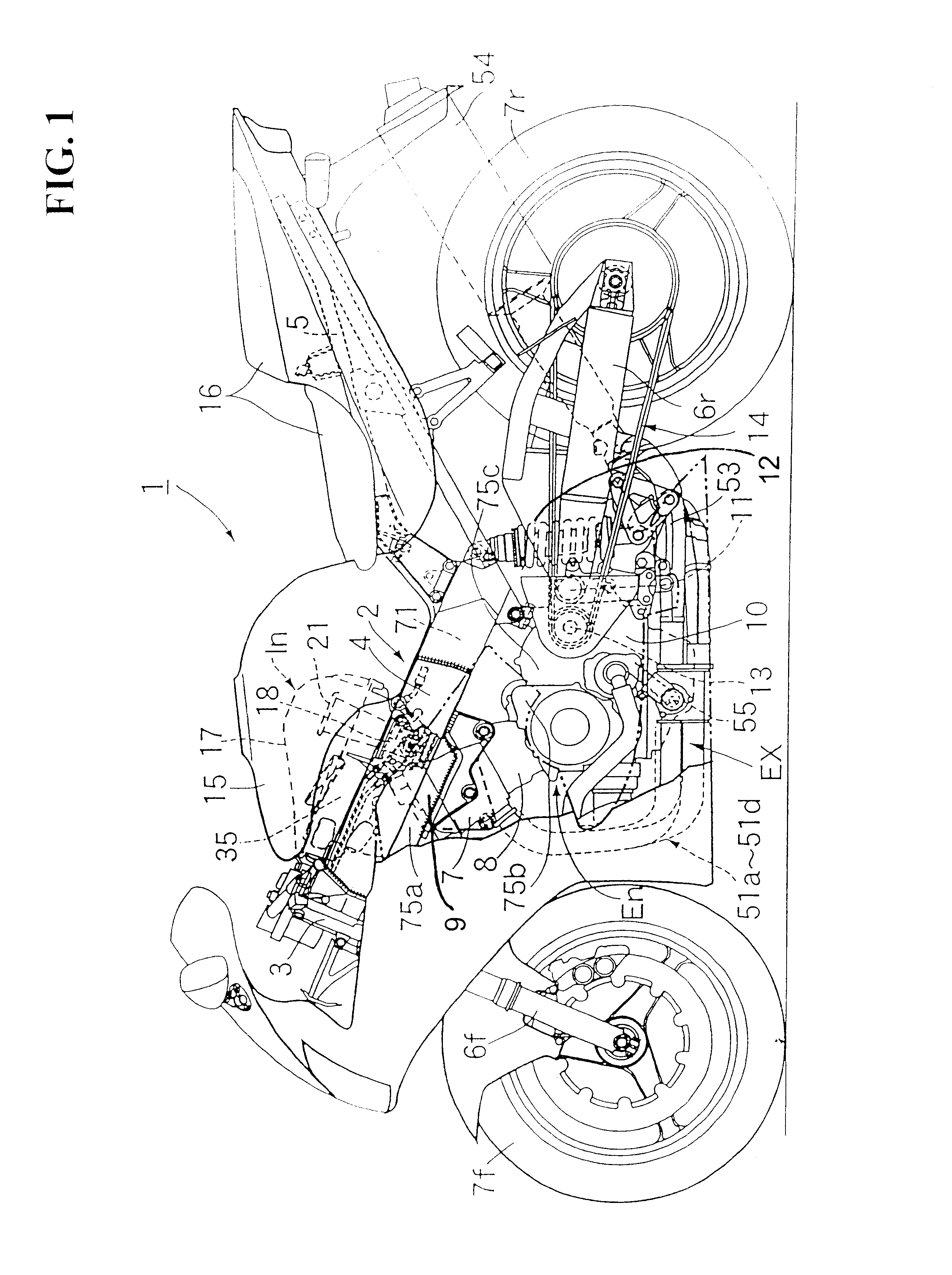
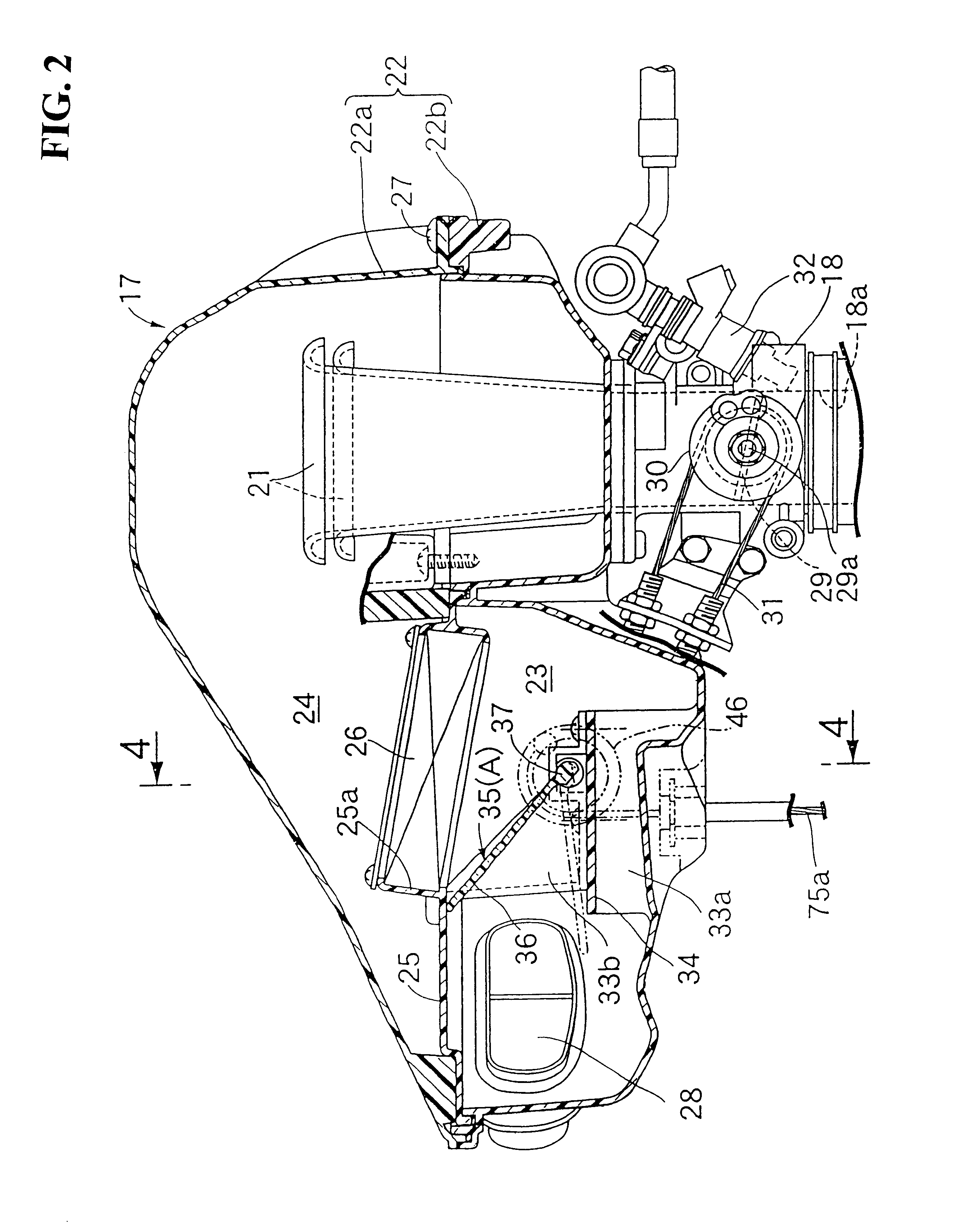
FIG. 1 is a side view of a motorcycle with an engine having an intake control device and an exhaust control device. FIG. 2 is a vertical sectional side view of a portion of an intake control device according to an embodiment of the present invention. FIG. 3 is a vertical sectional side view of a portion of an intake control device according to an embodiment of the present invention and corresponding to a different operational position than that of FIG. 2. FIG. 4 is a sectional view taken along line 4--4 of FIG. 2 according to an embodiment of the present invention. FIG. 5 is a sectional view taken along line 5--5 of FIG. 4 according to an embodiment of the present invention. FIG. 6 is a sectional view taken along line 6--6 of FIG. 4 according to an embodiment of the present invention. FIG. 7 is a perspective view of an exhaust system according to an embodiment of th...


PUM


Abstract

In an exhaust control valve having a valve housing and a valve body rotatably contained in the valve housing, a transmission member is fitted to an outer end of the valve shaft and protrudes from the outside of the valve housing. A bearing bushing for rotatably bearing an external circumferential surface of the valve shaft by its internal circumferential surface and rotatably bearing an end face of the valve body by its end face is mounted in the valve housing. The valve body is urged by load from a thrust spring for achieving a pressure contact seal condition between the opposed end faces of the bearing bush and the valve body.

Description

1. Field of the InventionThe present invention relates to an exhaust control valve, and more particularly to an exhaust control valve controlling the flow of exhaust gas from an internal combustion engine of a vehicle.2. Background ArtAn exhaust valve in which a bearing bushing for rotatably bearing a valve shaft and a seal member adjacent to the bearing bushing and making close contact with an external circumferential surface of the valve shaft are mounted in a valve housing has been taught by the background art. Japanese Pre-examination Patent Publication (KOKAI) No. 63-212728 (1988) shows an exemplary arrangement of this type of exhaust control valve.However, these types of exhaust control valve suffer from the following disadvantages. Since a bearing bushing and a seal member are both utilized, the number of component parts is increased. In addition, each of the bearing bushing and the seal member(s) provided exclusive functions. Finally, the seal member(s) are expensive, and th...

Claims


Application Information

Patent Timeline
Patent Type & Authority Patents(United States)
IPC IPC(8): F01N3/28F01N7/14F02D9/04F02D9/00F02B61/02F02B61/00F02M35/16F16K5/06F02M35/00F16K31/44F16K31/46F02M35/10F02B75/00F02B75/18F01N13/08F01N13/14F01N13/18F02D9/10F02D13/02
CPCF01N3/28F01N3/2853F01N13/14F02B61/02F02D9/04F02M35/10013F02M35/10039F02M35/10065F02M35/10216F02M35/10255F02M35/112F02M35/162F16K5/0647F16K31/465F01N2240/36F01N2410/10F01N2590/04F02B2075/1816Y10T137/86566
Inventor NAKAYASU, TETSUYASAGARA, MIKIOTAKAHASHI, KYOIWASE, NORITOSHIYAMADAMURAKAMI, ATSUSHI
Owner HONDA MOTOR CO LTD
Why Eureka
Try Eureka