Hybrid 3-D probe tracked by multiple sensors

a technology of multiple sensors and hybrid probes, applied in the field of hybrid 3d probes tracked by multiple sensors, can solve the problems of all such systems, limited accuracy and ease of operation, and inability to maintain line-of-sight,

Inactive Publication Date: 2003-08-26
STRYKER CORP
View PDF62 Cites 426 Cited by
  • Summary
  • Abstract
  • Description
  • Claims
  • Application Information

AI Technical Summary

Problems solved by technology

However, the limiting problem in all such systems, whether using active or passive light based markers, is maintaining line-of-sight between the markers (reflectors or emitters) and the multiple sensors.
For example, coordinate measurement machines (CMMs) and jointed mechanical arms do not require the marker to be within line of sight of the sensors, but they do require the tactile accessibility of a probe through rigid mechanical linkages, and this generally presents as much of a restriction on the accuracy and ease of operation as line-of-sight limitations.
Further, these mechanical means are generally slower and more awkward to use than light based systems.
The major drawback to such systems is that their accuracy is considerably degraded by the proximity of conductive objects, especially ferrous metals, and most especially large masses of ferromagnetic, materials, such as X-ray machines and other operating room apparatus.
It does not disclose continuous, dynamic registration of multiple (e.g. two) tracking systems during application, as will be discussed below.
Furthermore, it does not describe light based tracking of the magnetic system's field source generator.
Unfortunately, to determine the absolute position and angular orientation of the probe or other objects in three dimensional space, their linear and angular acceleration must be integrated twice with respect to time.
Furthermore, the slow rotation of Earth continuously affects all the angular measurements that are unaligned with the Earth's poles.
In other words, any tiny constant calibration error in the acceleration quickly accumulates into an unacceptably large error.
Therefore, by itself, an inertia-based mensuration system is not very practical for submillimeter measurements and the minute accelerations experienced by a hand-held probe.

Method used


Image

  • Hybrid 3-D probe tracked by multiple sensors
  • Hybrid 3-D probe tracked by multiple sensors
  • Hybrid 3-D probe tracked by multiple sensors

Examples


Embodiment Construction

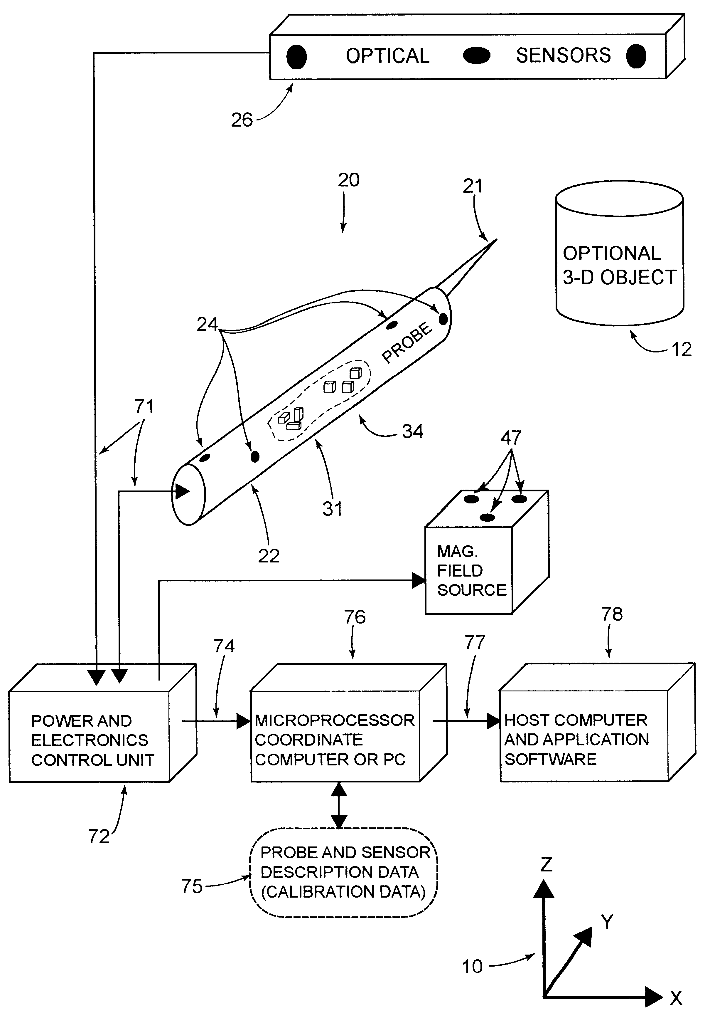
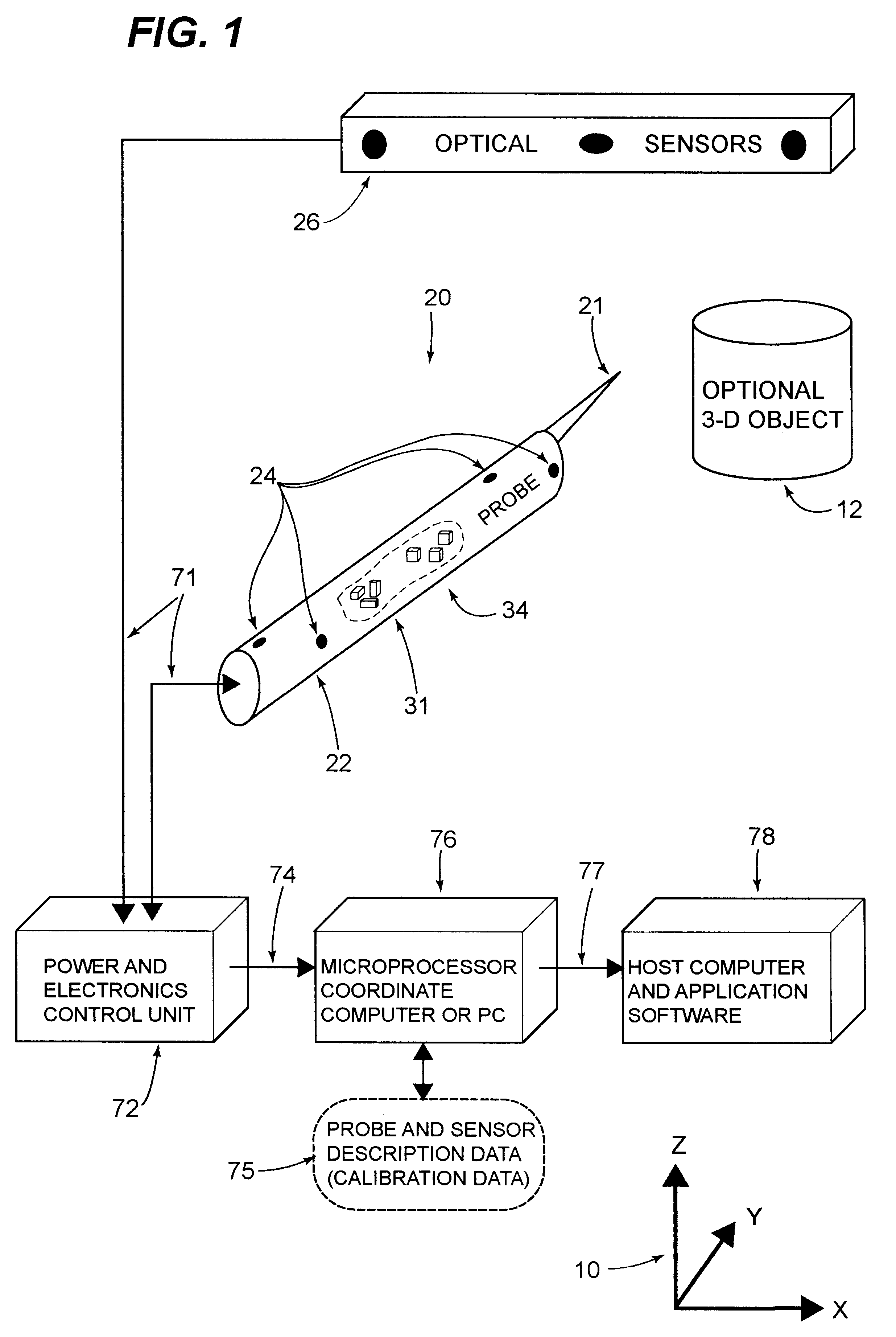
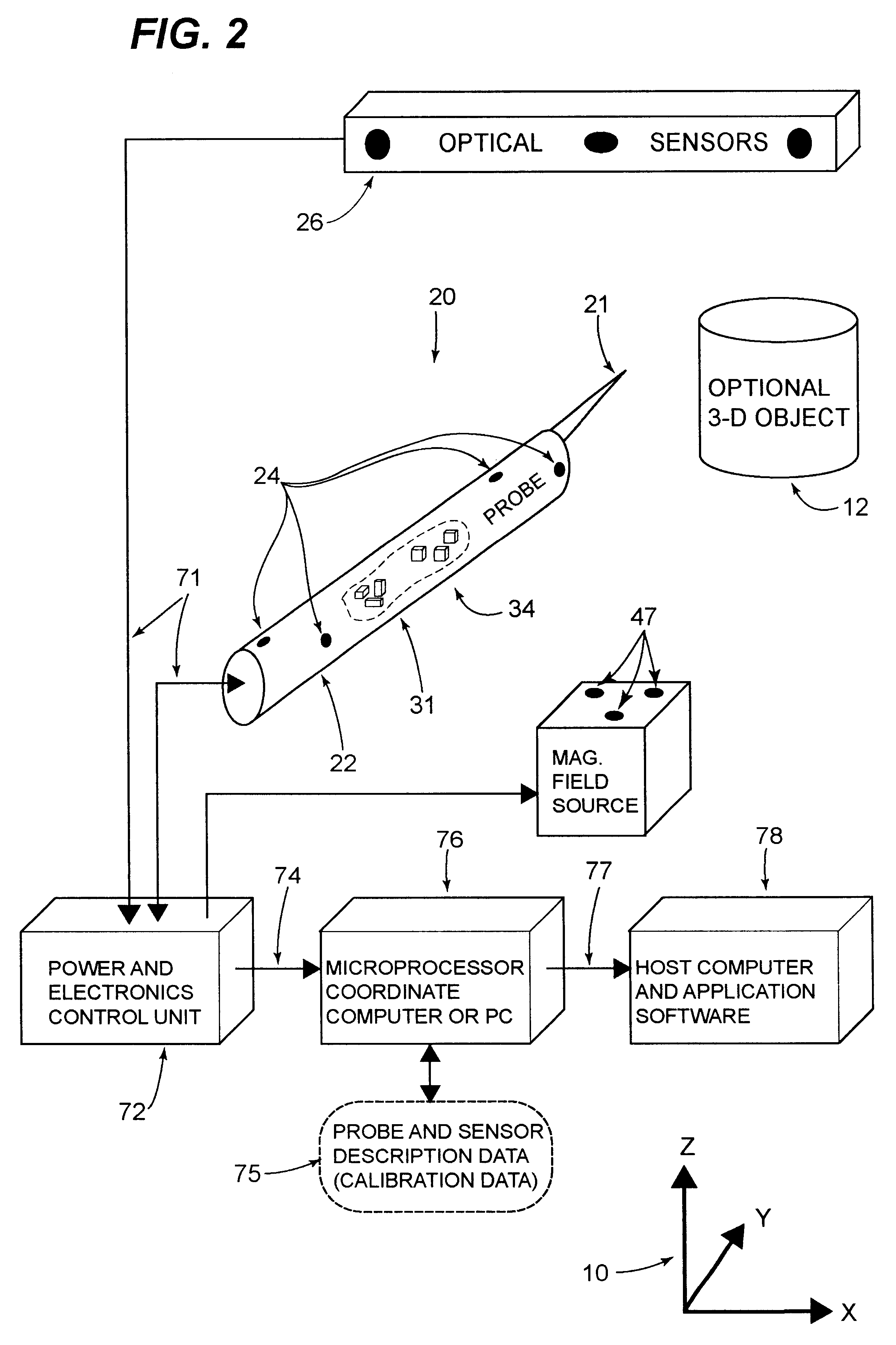
The invention will be described below with reference to the figures and the numbered individual components therein. In the description below, the specific construction, the number, and the arrangement of the components are intended for clarity of illustration and are not limitations on the scope of this invention. Other arrangements or quantities of the components constitute alternative specific embodiments of the same method, apparatus and system.

FIGS. 1 and 2 illustrate two alternative preferred embodiments of the present invention. FIG. 3 depicts as a flowchart the major steps 81 . . . 99 of the program that operates the coordinate computer 78 and other peripheral equipment. These program steps apply to either or both of the two embodiments and even to an embodiment that combines the components of those two.

With reference to FIG. 1, the apparatus includes a 3-D light based measurement system, such as the FlashPoint 5000 built by Image Guided Technologies, Inc., of Boulder, Colo. ...


PUM


Abstract

This invention is a system that tracks the 3-dimensional position and orientation of one or more bodies (20) in a volume by a light based as well as at least one non-light based mensuration sub-system. This overcomes the limitation of light based mensuration systems to the necessity of the bodies (20) to be in constant line-of-sight of its light based position sensors (26). The invention possesses most of the accuracy and stability of its light based position measurement sub-system (24, 26, 72), but can also work without direct line of sight either for short periods of time or within certain parts of the volume. It does so by incorporating other sensors (31, 34), such as inertial or magnetic, which are frequently recalibrated against the light based sub-system (24, 26, 72) while the bodies (20) are visible by the light based sub-system (24, 26, 72).

Description

This invention relates to an improvement in systems for measuring the position and orientation of probes and other rigid bodies being tracked in 3-dimensional (3-D) space. The improvements engendered by this invention can be applied to 1-dimensional and 2-dimensional measurement systems, but the description herein describes the invention in the more general context of measurements in three dimensions.DESCRIPTION OF THE BACKGROUND ARTVarious methods and systems exist in the art to track the locations of points (markers) in a spatial volume defined by some 3-D coordinate system. By attaching multiple markers to bodies, even moving bodies, the orientation as well as the position of the bodies, individually or in relationship to each other, can be determined. For example, such bodies may be hand-held probes, moveable rigid objects, or semi-rigid portions of human anatomy.Hereinafter, the position of a body means its 3-D location plus its 3-D orientation about that location. One common w...

Claims


Application Information

Patent Timeline
Patent Type & Authority Patents(United States)
IPC IPC(8): G01S5/16G01S5/00A61B19/00G01B7/00G01B11/00G01B11/03G01C21/16G01S5/02
CPCA61B19/5244G01C21/165G01S5/16G01S5/163A61B2019/4894A61B2019/507A61B2019/5248A61B2019/5251A61B2019/5255A61B2019/5495G01S5/021G01S5/0263A61B2090/0818A61B2034/2048A61B2034/2055A61B2090/3995A61B34/20A61B2034/107A61B2034/2051
Inventor SCHULZ, WALDEAN A.FAUL, IVAN
Owner STRYKER CORP
Why Eureka
Try Eureka