Process for manufacturing a blade of a cutting tool and product manufactured therewith

a technology of cutting tools and blades, which is applied in the direction of cutting tools, furnace types, applications, etc., can solve the problems of knife becoming unsuitable for the intended use, hardening of the boundary layer, and affecting the use effect of the kni

Inactive Publication Date: 2003-09-02
ZWILLING J A HENCKELS
View PDF15 Cites 48 Cited by
  • Summary
  • Abstract
  • Description
  • Claims
  • Application Information

AI Technical Summary

Problems solved by technology

Thus, the formation of such a boundary layer has proven to be disadvantageous, in particular in the manufacturing of a knife blade, since use of the knife together with a hard cutting substrate of, for instance, glass or ceramic can lead to localized chipping of the boundary layer.
As the result of the chipping of the hardened boundary layer, the edge area of the blade is destroyed, and as a result the knife becomes unsuitable for the intended use.
A shock-like stress on the blade, for instance, when it is dropped from a certain height and impacts on a hard surface, can disadvantageously lead to a chipping of the hardened boundary layer.
Previously known processes of manufacturing a blade additionally have the disadvantage that they are in some instances quite elaborate and thus cost-intensive because, depending on the process used to harden the boundary layer, subsequent machining by means of, for instance, grinding is necessary.
Another consequence of this is that automation of the previously employed processes can be produced only with difficulty.

Method used


Image

  • Process for manufacturing a blade of a cutting tool and product manufactured therewith
  • Process for manufacturing a blade of a cutting tool and product manufactured therewith
  • Process for manufacturing a blade of a cutting tool and product manufactured therewith

Examples


Embodiment Construction

The present invention will now be discussed in detail with reference to the drawings.

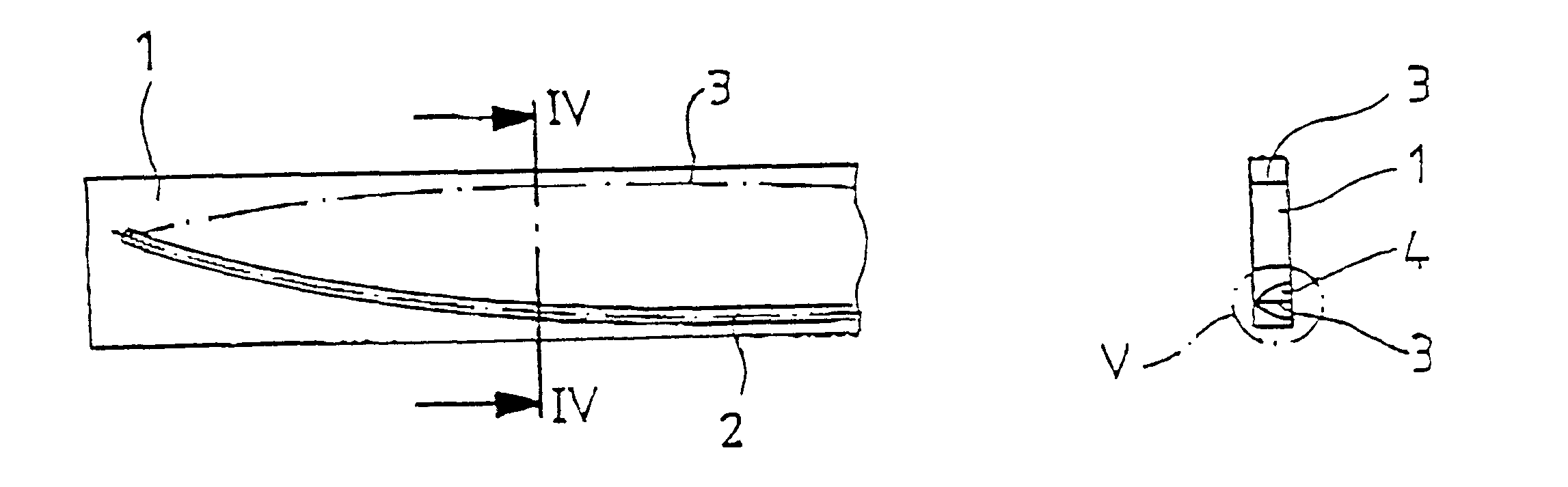
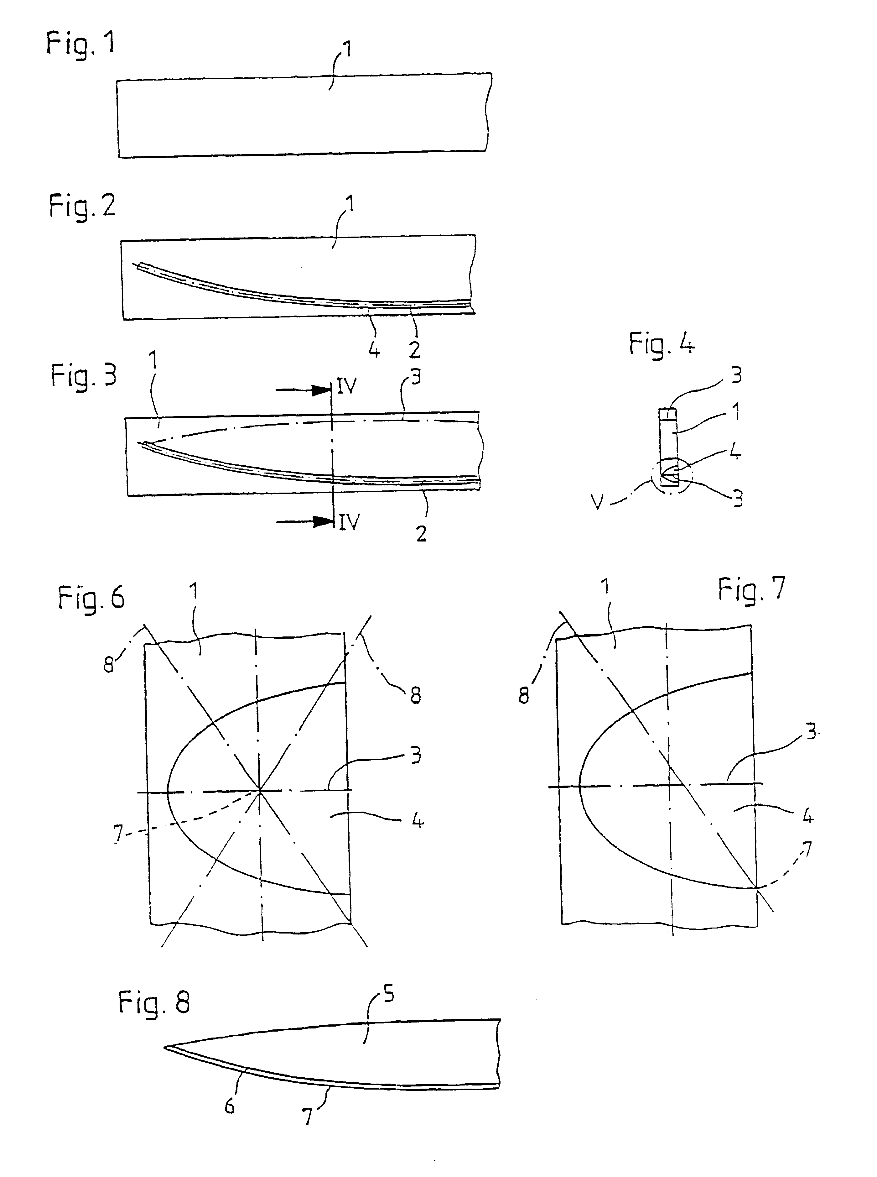
In FIG. 1, the initial workpiece labeled 1, from which the blade 5 of a cutting tool, in particular, a knife, is manufactured according to the process of the invention, is schematically shown. The initial workpiece 1 has a defined length, width and height and preferably consists of an alloyed steel such as X 20 Cr 13. Other suitable metals can be used as will be apparent to those skilled in the art.

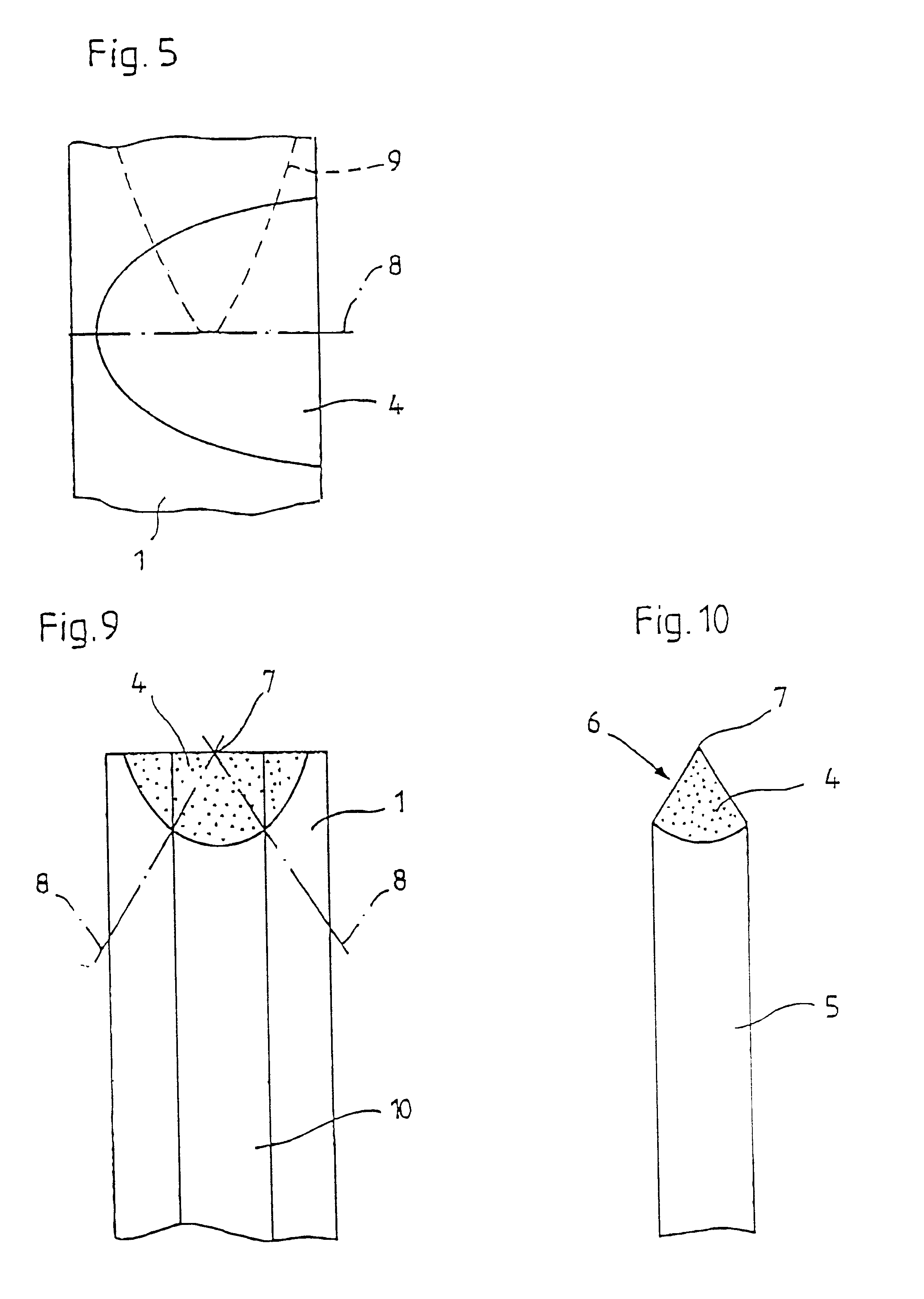
In the first process step, a laser treatment of the blade base material is performed along the curve contour 2 determined by the ultimate edge of the blade. This is shown in FIG. 2. In particular, laser beam alloying and laser beam dispersion are suitable laser treatment processes. Both processes permit the targeted influencing of material properties by melting the base material and including suitable additive materials such as chromium, tungsten, molybdenum, titanium, vanadium, tantalum, nickel, cobalt o...


PUM

PropertyMeasurementUnit
thicknessaaaaaaaaaa
angleaaaaaaaaaa
structureaaaaaaaaaa

Abstract

A method for manufacturing a blade of a cutting tool, in particular, a knife. In order to create a process with which influence is to be exerted in a targeted manner on the technological material properties of the blade and material chipping to be avoided, as well as permitting economical manufacturing, a process is carried out by treating a blade base material with a laser in a first process step along a curve contour determined by the final edge of the blade and, in a second process step, the edge of the blade is formed, in particular, cut to shape, along the curve contour determined by the final blade form inside the laser-treated area, or the blade base material is machined in a first process step by punching or trimming to form the final edge, subsequently the laser treatment is performed in a second process step on the narrow side forming the final edge and finally, in a third process step, the blade is formed, in particular, ground, inside the laser-treated area.

Description

INTRODUCTION AND BACKGROUNDThe present invention pertains to a process for manufacturing a blade of a cutting tool, in particular, a knife. In a further aspect, the invention additionally pertains to a blade manufactured according to the process.Processes of manufacturing a blade of a cutting tool are known from the prior art. First of all, starting from a precursor material present in the form of a flat material, a blade blank whose geometric dimensions approximately correspond to those of the ultimate finished blade form is produced by punching. The machining of the precursor material can be accomplished by, for instance, processes of punching technology, pressure forming, bending forming or shearing forming. The cutting of a blade blank to size is also known from the prior art. In a second manufacturing stage, the fine machining of the blade blank then takes place. The appropriate blade contour on the one hand and the edge area on the other are formed, the appropriate grinding ag...

Claims


Application Information

Patent Timeline
Patent Type & Authority Patents(United States)
IPC IPC(8): B23P15/40B26B9/00B23K26/00B23K26/34B23K26/38C21D1/09C21D9/18
CPCB23P15/40B26B9/00
Inventor DROESE, JOACHIMGRAFE, HORST
Owner ZWILLING J A HENCKELS
Why Eureka
Try Eureka