Integrated twist-grip switch

a technology of twist-grip switch and twist-grip switch, which is applied in the direction of linear shaft, cycle control system, steering device, etc., can solve the problems of occupying space in the region of the switch housing of the predominantly plastic construction

Inactive Publication Date: 2003-09-09
SRAM
View PDF11 Cites 33 Cited by
  • Summary
  • Abstract
  • Description
  • Claims
  • Application Information

AI Technical Summary

Benefits of technology

The bearing tube is prolonged in the direction of the grip end piece. The grip end piece is fixed to the bearing tube by a chemical overmolding connection. In contrast to the prior art described, the bearing tube of the present invention is not connected fixedly in terms of rotation to the elastic twist-grip part and the winding reel. Rather, the bearing tube serves as a mounting for these and forms, with the fixed intermediate ring, the necessary axial abutment for the twist-grip part connected fixedly in terms of rotation to the winding reel.
According to the present invention, the problem of space is solved by combining two functions and direct interaction between the respective operating elements. That is, the present invention includes radially elastic tongues arranged on the bearing tube which are equipped at the end with a locking profile to form a nonrotatable and nondisplaceable positive connection with a counterprofile on the switch housing. The twist-grip part, the winding reel, and also the switch housing together with the switch mechanism may be lined up via these elastic tongues for forming a preassembly which is mountable onto the bearing tube. This preassembly is secured against inadvertent breaking apart by the snap connection between the bearing tube and switch housing. The number of components of the twist-grip switch needed for the final mounting step on the handlebar is thereby markedly reduced. The arrangement of the clamping clip in the inside diameter of the switch housing with the accompanying screw allows the complete twist-grip switch to one piece ready for mounting. Tightening the screw on the clamping clip ensures a secure fit of the twist-grip switch, including a grip end piece, on the handlebar. The bearing tube or the twist-grip part together with winding reel may be demounted again or uncoupled from the switch housing only after the removal of the clamping clip. To ensure a play-free fit on the handlebar, the inside diameter on the bearing tube and on the grip end piece has a correspondingly narrow dimension or tolerance. Controlled deformation of the inner region may also be used to eliminate the sensitivity to tolerance. Thus, the inner surface of the bearing tube may include at least a part region, preferably axially adjacent to the elastic tongues, having a shape which is not circular, but oval or polygonal to achieve a play-free fit during adaption to the round handlebar cross section. The same play-free fit may be achieved when this bearing tube inner region is equipped with narrow elevations which run essentially in the axial direction which undergo deformation during mounting and then fit firmly. Perforations may be arranged on the bearing tube in the region of the overlap of the grip end piece so that when the grip end piece is being attached material of the grip end piece projects into the inside diameter of the bearing tube. During assembly of the preassembly onto the handlebar, the material projecting into the inside diameter experiences a deformation and is pressed on.
The bearing tube is prolonged in the direction of the grip end piece. The grip end piece is fixed to the bearing tube by a chemical overmolding connection. In contrast to the prior art described, the bearing tube of the present invention is not connected fixedly in terms of rotation to the elastic twist-grip part and the winding reel. Rather, the bearing tube serves as a mounting for these and forms, with the fixed intermediate ring, the necessary axial abutment for the twist-grip part connected fixedly in terms of rotation to the winding reel.

Problems solved by technology

However, before installation of the preassembled twist-grip switch on the handlebar tube, it is possible for the still releasable locking connection to loosen, thereby breaking apart the preassembly of the components and incurring an increase in the outlay in terms of assembly.
Furthermore, switch housings constructed predominantly from plastics have problems of space in the region of a switch housing.
The plastic material alone does not have the strength necessary for this purpose, or creeping processes of the material are detrimental to a permanently reliable fixing of the switch on the handlebar tube.
However, the strict separation between the interlocking of other components of the switch with the housing and the clamping of the switch to the handlebar requires a greater space requirement.

Method used


Image

  • Integrated twist-grip switch
  • Integrated twist-grip switch
  • Integrated twist-grip switch

Examples


Embodiment Construction

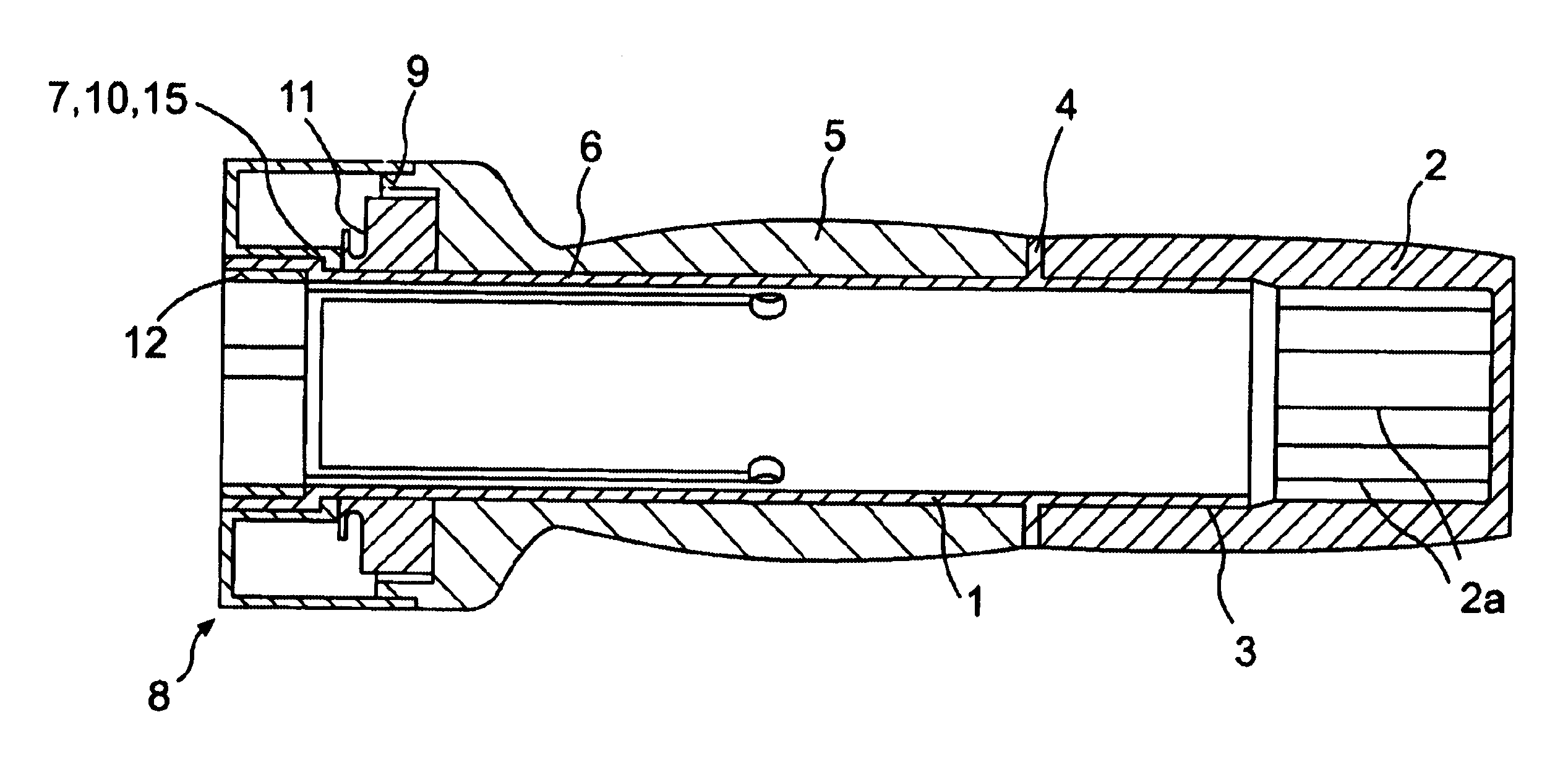
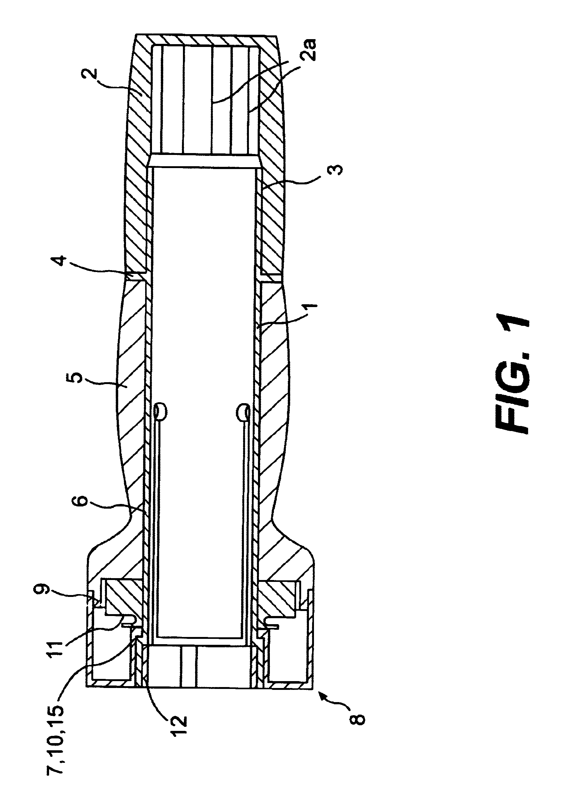
FIG. 1 is a longitudinal sectional view of a twist-grip switch according to the present invention (the twist-grip switch may also be referred to as a twist-grip shifter). The components are arranged essentially around a bearing tube 1 made of hard plastic. The inside diameter of the bearing tube 1 is dimensioned to ensure a play-free fit on a handlebar tube of a bicycle. A grip end piece 2 made of an elastomeric material is rigidly connected to the bearing tube 1 by, for example, an overmolding connection 3 so that the grip end piece 2 is fixed with respect to rotation relative to the bearing tube 1. That portion of the rotationally fixed grip end piece 2 which projects beyond the bearing tube 1 has a smaller inside diameter than the bearing tube 1, so that it fits on the handlebar end free of play or with tension. The outer contour of the grip end piece 2 has a slightly convex shape to improve the ergonomics.

Furthermore, the inside diameter surface of the grip end piece 2 in the po...


PUM


Abstract

A twist-grip switch for the actuation of bicycle gears is arranged in the grip region of a handlebar is fixed thereto by a clamping clip. The switch components, such as the grip end piece, twist-grip part, winding reel and switch housing, are arranged around the central bearing tube and form a complete grip unit. The bearing tube fits tautly on the handlebar and on one side is rigidly connected to the grip end piece by an overmolding connection and on the other side is fixed to the switch housing by means of a snap connection. The clamping clip prevents the snap connection from being opened in the mounted state. Furthermore, the grip end piece reliably assumes the intended position on the handlebar tube in relation to the switch housing, and it cannot be removed from this position by forces acting on it.

Description

1. Field of the InventionThe present invention relates to an integrated twist-grip switch for the shifting of bicycle gears, such as multi-speed hubs or derailleur shifts.2. Description of the Related ArtTwist-grip switches for the control of bicycle gears are generally preassembled and mounted on the bicycle, i.e., pushed onto the handlebar tube, in the preassembled state. The twist-grip switch is then adjusted and fixed on the handlebar. The attachment to the handlebar is usually carried out by a clamping device.In a preassembled twist-grip switch, a plurality of switch components are assembled together, and a locking connection is often used, which is not releasable after the preassembled twist-grip is mounted on the handlebar tube.However, before installation of the preassembled twist-grip switch on the handlebar tube, it is possible for the still releasable locking connection to loosen, thereby breaking apart the preassembly of the components and incurring an increase in the ou...

Claims


Application Information

Patent Timeline
Patent Type & Authority Patents(United States)
IPC IPC(8): B62K23/00B62K23/04B62M25/04
CPCB62K23/04Y10T74/20828Y10T74/20438
Inventor WESSEL, ROBERT
Owner SRAM
Why Eureka
Try Eureka