Eureka AIR delivers breakthrough ideas for toughest innovation challenges, trusted by R&D personnel around the world.

Surgical retractor securing apparatus

Inactive Publication Date: 2003-09-09
CAREFUSION 2200 INC
View PDF15 Cites 37 Cited by
  • Summary
  • Abstract
  • Description
  • Claims
  • Application Information

AI Technical Summary

Benefits of technology

In its most general sense, the present invention overcomes the shortcomings and limitations of the prior art in any of a number of generally effective configurations. An aspect of this invention is to provide a scalp hook locking device that is capable of quickly and dependably locking the elasticized band of a scalp hook to an external fixation device.

Problems solved by technology

Due to the extremely delicate nature of the surgery, the surgical field, that is, the patient's head, must be held entirely immobile throughout the often lengthy procedure.
Secondly, various tissues of differing tensile strengths, ranging from relatively strong scalp tissue to exceedingly delicate brain structures, must be retracted to allow surgical access during the procedure.
While effectively maintaining the scalp flap away from the surgical site, this means of attaching the elasticized band of the scalp hook retractor to the halo device creates several recurring problems.
First, the attachment of the elasticized band of the scalp hook retractor to the halo device by tying or looping creates a potentially insecure attachment to the halo device, such that the elasticized portion of the scalp hook retractor may slip during surgery.
Due to the extremely delicate nature of the surgery, such sudden motion in the surgical field can have disastrous consequences for the patient.
However, to achieve such radial adjustment, repositioning the scalp hook retractor requires untying or unlooping the elasticized band and then re-tying or re-looping the elasticized band, a cumbersome and time consuming procedure, particularly if a plurality of scalp hooks need to be readjusted.
Third, fixation by tying or looping makes it difficult for the surgeon to effectively select the amount of tension desired, as the length, and therefore tension, of the elasticized material will often change while manually tying or looping the elasticized material.
While some of the prior art devices attempted to improve the state of the art of surgical retractor retaining devices, none has achieved a cost optimized capability that has an easy to fabricate and convenient to use arrangement.

Method used


Image

  • Surgical retractor securing apparatus
  • Surgical retractor securing apparatus
  • Surgical retractor securing apparatus

Examples


example

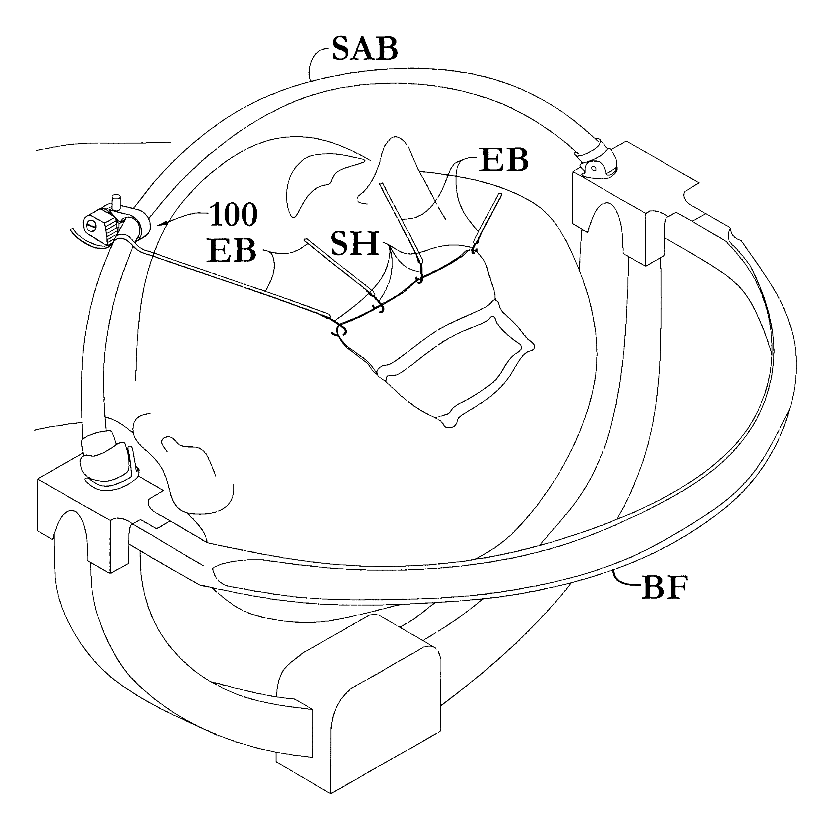
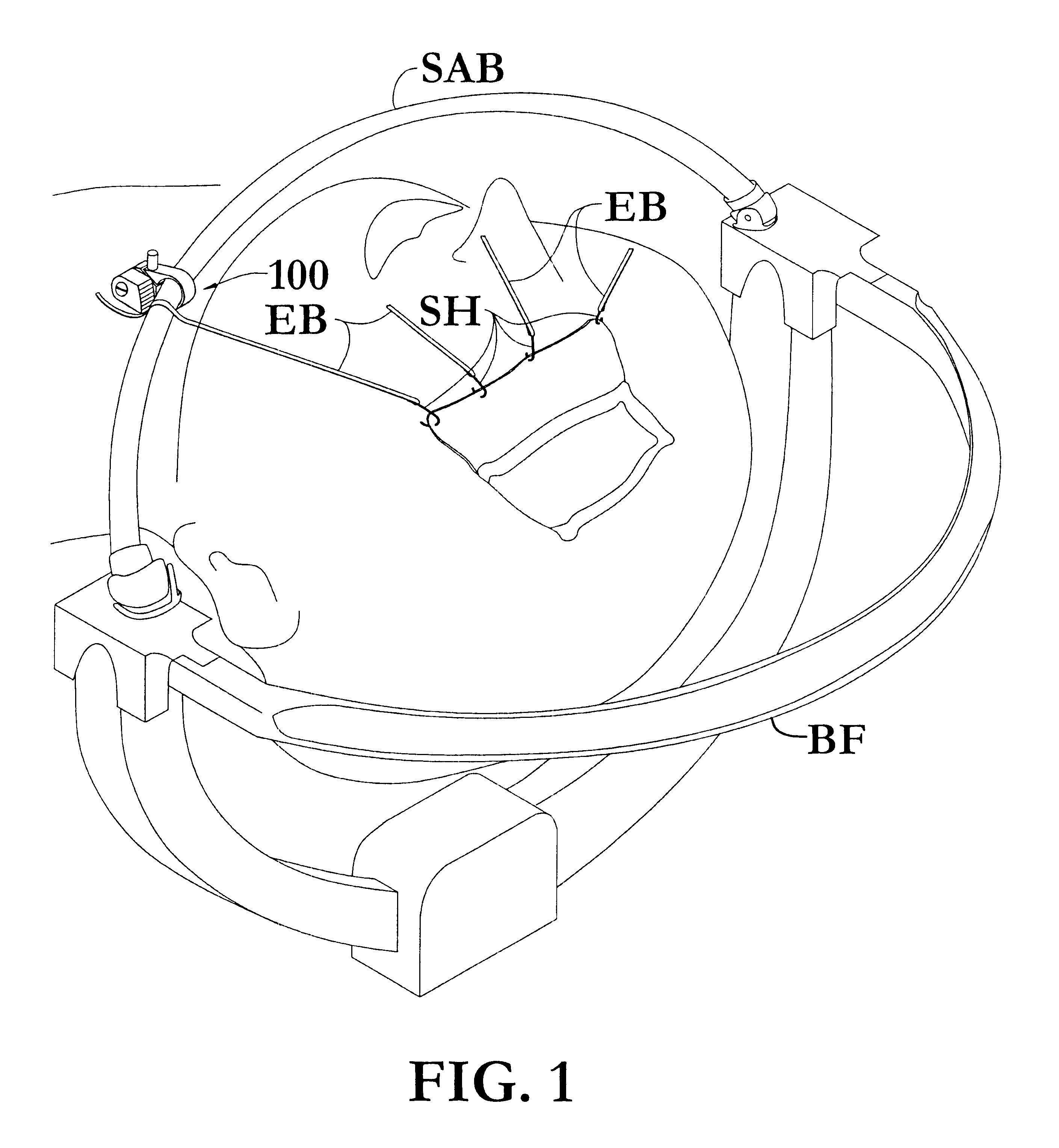
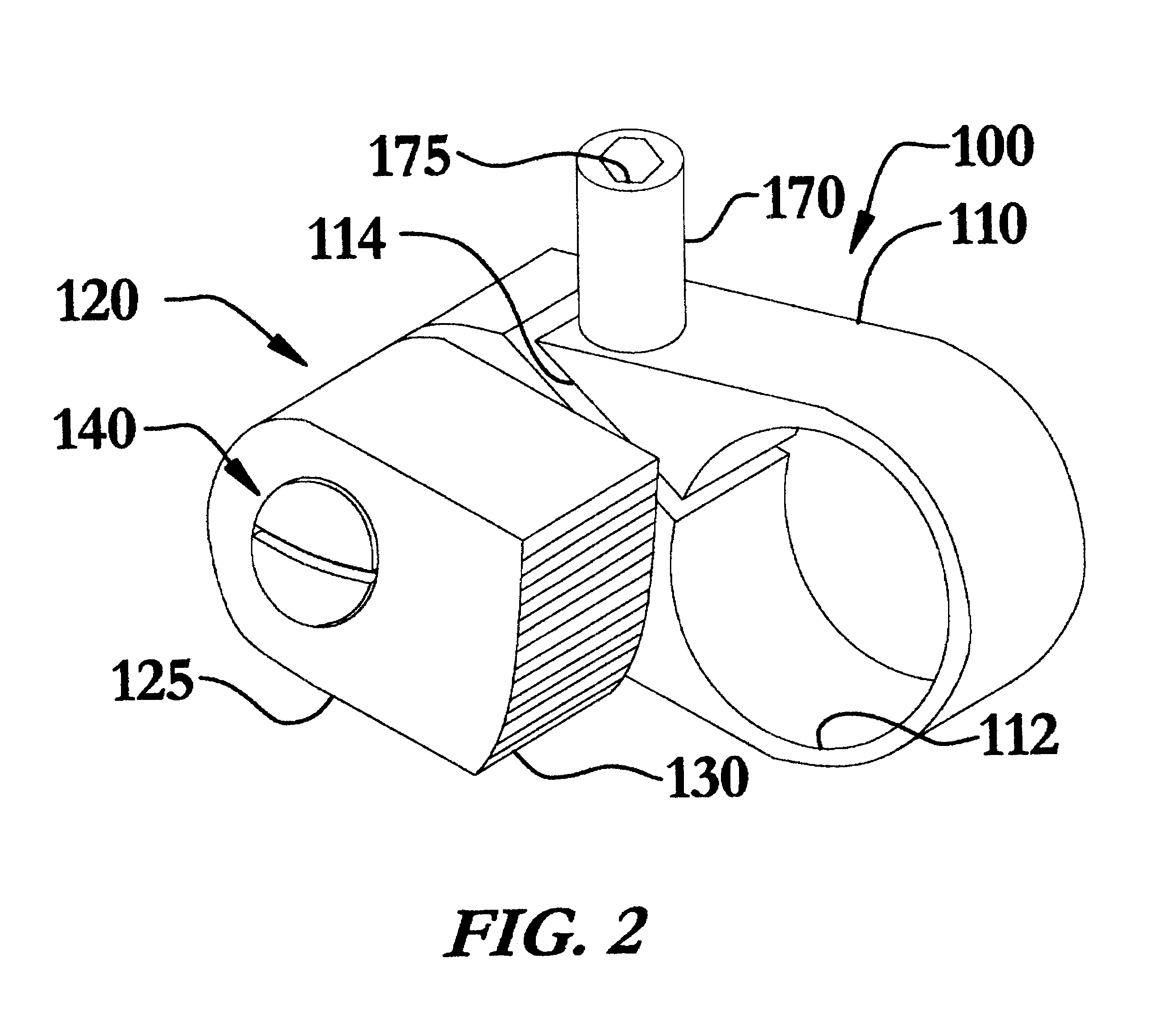
To demonstrate and evaluate the surgical retractor securing apparatus according to the invention, a procedure was conducted upon a cadaver. The cadaver head was fixated in a Spetzler Headrest in the usual fashion. A surgical accessory bar was attached and six securing apparatuses similar to FIG. 2, were placed on the bar and positioned parallel to the proposed entry site of the skull. A physician then made an incision on the skull and used the six scalp hooks with rubber bands to retract the scalp back from the wound site. The distal ends of the rubber bands were placed in the securing apparatuses under tension. The securing apparatuses all consistently held (locked) the rubber bands without slipping. The physician then proceeded to increase the load on the hooks by moving the accessory bar away from the incision site, thereby stretching the rubber bands. This was done to the point where physical damage to the scalp would normally occur. The rubber bands were held secure even under ...


PUM


Abstract

A surgical retractor securing apparatus includes an adjustable securing device which attaches the apparatus to the surgical accessory bar of a halo style head fixation device and a capture assembly that releasably engages the elasticized band of a scalp hook retractor. The adjustable securing device compressively grips along a portion the length of a surgical accessory bar or otherwise attaches to an external support, providing a plurality of attachment points. The capture assembly may include a pivotable cam that releasably grips the elasticized band of a scalp hook retractor by compressing the band between the gripping cam and the surgical accessory bar or other external support.

Description

The invention relates to the field of surgical instruments, particularly, a device for anchoring surgical retractors during operative procedures.Medical professionals have long-recognized the need for surgical instruments that can be reliably placed and retained in position during surgery. What has been needed but was heretofore unavailable are surgical retractor anchoring devices that reliably retain retractors and are easily engaged and disengaged during surgery. Such long-felt needs have been particularly prevalent in the field of intracranial neurosurgery.Surgical retractors designed to retract tissues during surgery may be generally classified into two types; those which are designed to be held free and manipulated by an assistant during surgery, and those that are attached to the patient, the operating table or other external support. This later class is styled in the art as self-retaining retractors. A common style of self-retaining retractor is exemplified by that disclosed ...

Claims


Application Information

Patent Timeline
IPC IPC(8): A61B17/02A61B19/00
CPCA61B17/0293A61B17/02A61B19/26A61B2017/0287A61B90/50
Inventor BASS, DANIELWIEDENMAIER, UDO
Owner CAREFUSION 2200 INC
Why Eureka
Eureka Blog
Learn More