Multi-mode multi-propellant liquid rocket engine

a multi-propellant, liquid rocket technology, applied in the direction of rocket engine plants, machines/engines, cosmonautic vehicles, etc., can solve the problems of significant design complications, cost increases, and few of the known rocket engines

Inactive Publication Date: 2003-09-16
MSE TECH APPL
View PDF15 Cites 63 Cited by
  • Summary
  • Abstract
  • Description
  • Claims
  • Application Information

AI Technical Summary

Problems solved by technology

Known rocket engines, however, operate at efficiencies that are far from the optimum, particularly for single stage earth to orbit operation.
While many solutions for the enhancement of liquid fuel rocket engines have been proposed, few of them have been implemented.
Most innovations lead to significant design complications and cost increases which offset their potential benefits.
Single-stage-to-orbit (SSTO) launchers are not feasible because idling groups of engines must be carried.
Multistage configurations further result in high launch costs and prevent introduction of reusability.
The use a fuel efficient LOX / LH2 engine as the only thruster for SSTO launchers is unlikely to be successful because such an engine is not efficient when used as a low altitude thruster.
The engine further includes several turbocompressors to compress air to a delivery pressure of several hundred bars, a series of heat exchangers, and turbopumps, all of which make the engine complicated and expensive to produce and operate and its mass prohibitively high.
No real attention is paid, however, to complications to the engine resulting from the necessary additional pumps, plumbing, valves, etc.
As a result, the LACE shows inadequate performance gain and / or prohibitively complicated and heavy design.

Method used


Image

  • Multi-mode multi-propellant liquid rocket engine
  • Multi-mode multi-propellant liquid rocket engine
  • Multi-mode multi-propellant liquid rocket engine

Examples


Embodiment Construction

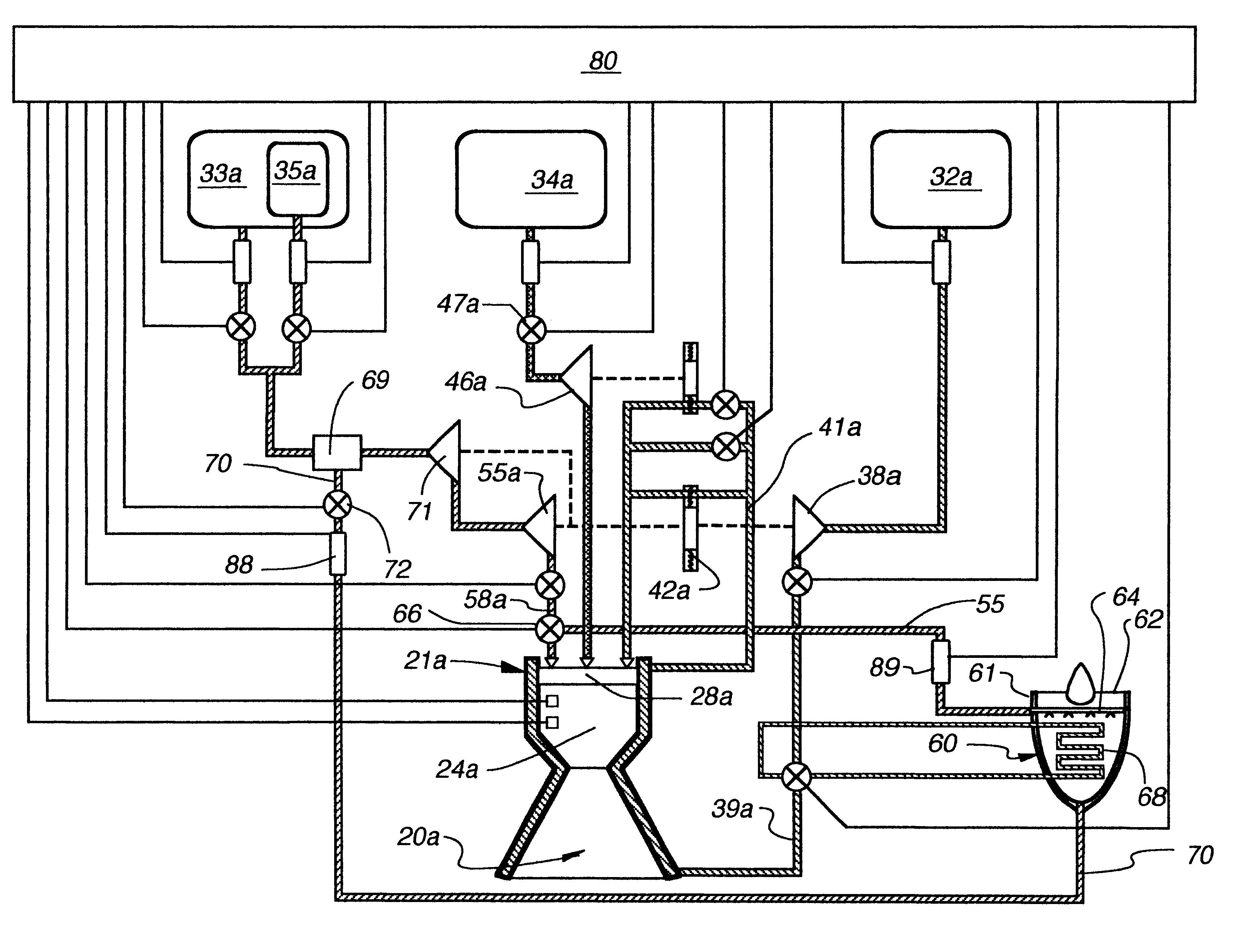
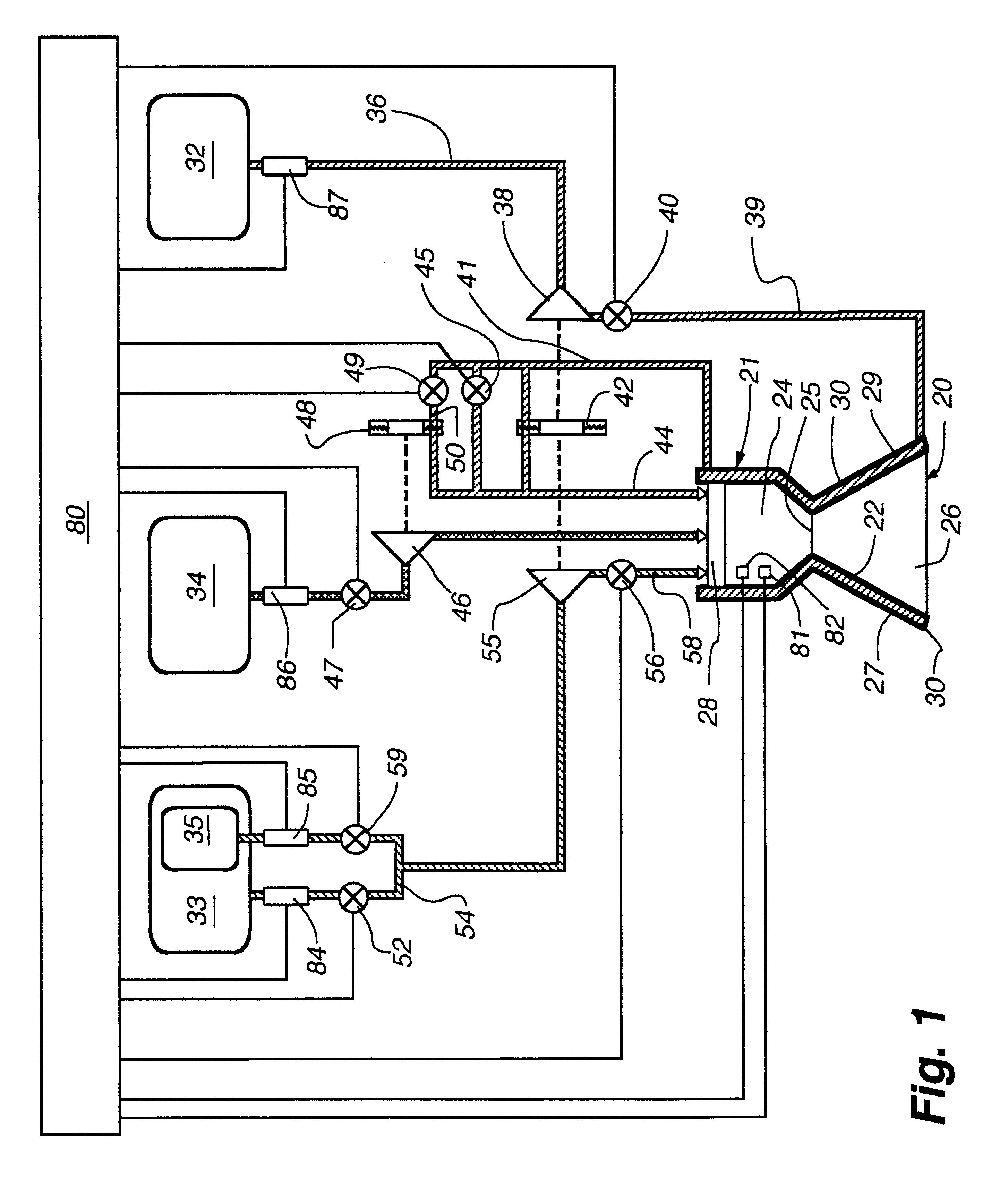
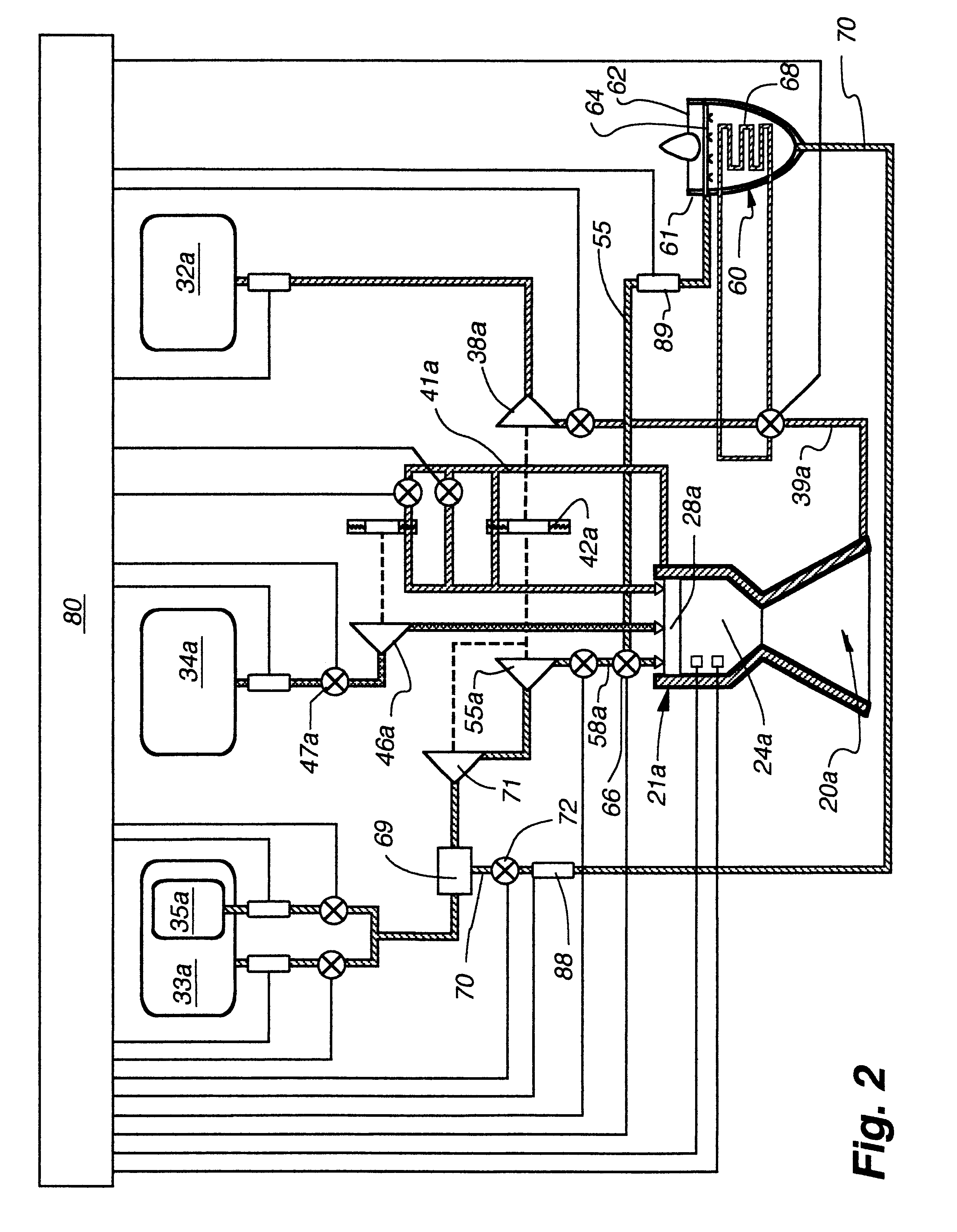
The present invention is embodied in a new, novel and unobvious multi-propellant, multi-mode-rocket engine 20 as shown in FIG. 1, and in the method of operation thereof. The rocket engine 20 is formed by a combustor 21 having a shell 22 defining a cylindrical combustor chamber 24 opening at one end through a throat 25 into a wide nozzle 26. At its other end the chamber 22 supports an injector head 28 through which propellant fuel and oxidizer components are introduced into the combustor chamber 24 in which they are ignited and burn to produce exhaust gases to provide the desired thrust.

The combustor 21 is provided with an external cooling jacket or shell 29 defining a cooling passage 30 adapted to receive one of the fuel components such as liquid hydrogen as a coolant for the nozzle 26 and combustor 21.

Propellant components in the form of fuels and oxidizers are fed to the injector head from storage tanks therefor. Referring to FIG. 1, propellant component storage tanks include a li...


PUM


Abstract

A multi-mode multi-propellant rocket engine capable of operating in a plurality of selected modes.Propellant components may include liquid hydrogen, liquid hydrocarbon, liquid oxygen, liquid fluorine, and liquid air. The liquid oxygen and the liquid air are stored in separate tanks are mixed in a dedicated mixer prior to their injection into the combustion chamber.

Description

1. Field of the InventionThe present invention relates to liquid propellant rocket engines and particularly to multi-mode multi-propellant single stage earth to orbit or suborbital rocket engines.2. Description of the Prior ArtRocket propulsion for earth to orbit launch vehicles is currently the only practical choice. Known rocket engines, however, operate at efficiencies that are far from the optimum, particularly for single stage earth to orbit operation. While many solutions for the enhancement of liquid fuel rocket engines have been proposed, few of them have been implemented. Most innovations lead to significant design complications and cost increases which offset their potential benefits. As a result, principles discovered early in the 20th century, such as for example multistage rockets, still provide the main basis for modern rocket launchers. It is well known from rocket theory that launcher efficiency can be increased if high thrust, dense propellant, moderate specific imp...

Claims


Application Information

Patent Timeline
Patent Type & Authority Patents(United States)
IPC IPC(8): B64G1/22B64G1/40F02K9/00F02K9/42F02K9/56F02K9/46
CPCB64G1/401B64G1/402F02K9/42F02K9/46F02K9/56
Inventor BALEPIN, VLADIMIR V.
Owner MSE TECH APPL
Why Eureka
Try Eureka