
Chisel holder changing system

a technology of changing system and chisel holder, which is applied in the direction of couplings, cutting machines, basic electric elements, etc., can solve the problem of excessive stress and damage to the chisel holder

Inactive Publication Date: 2003-09-16
WIRTGEN GMBH
View PDF11 Cites 60 Cited by
  • Summary
  • Abstract
  • Description
  • Claims
  • Application Information

AI Technical Summary

Benefits of technology

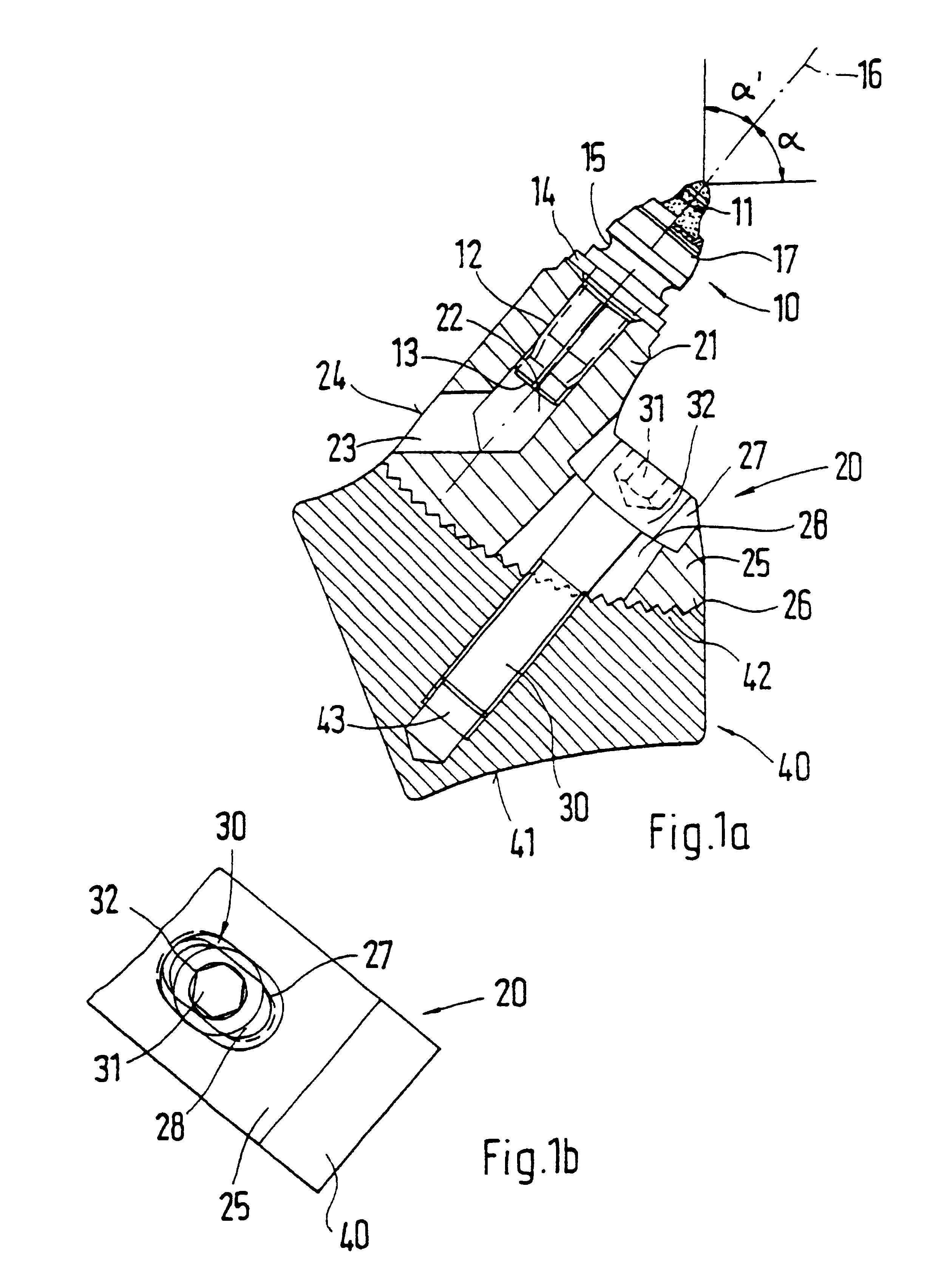
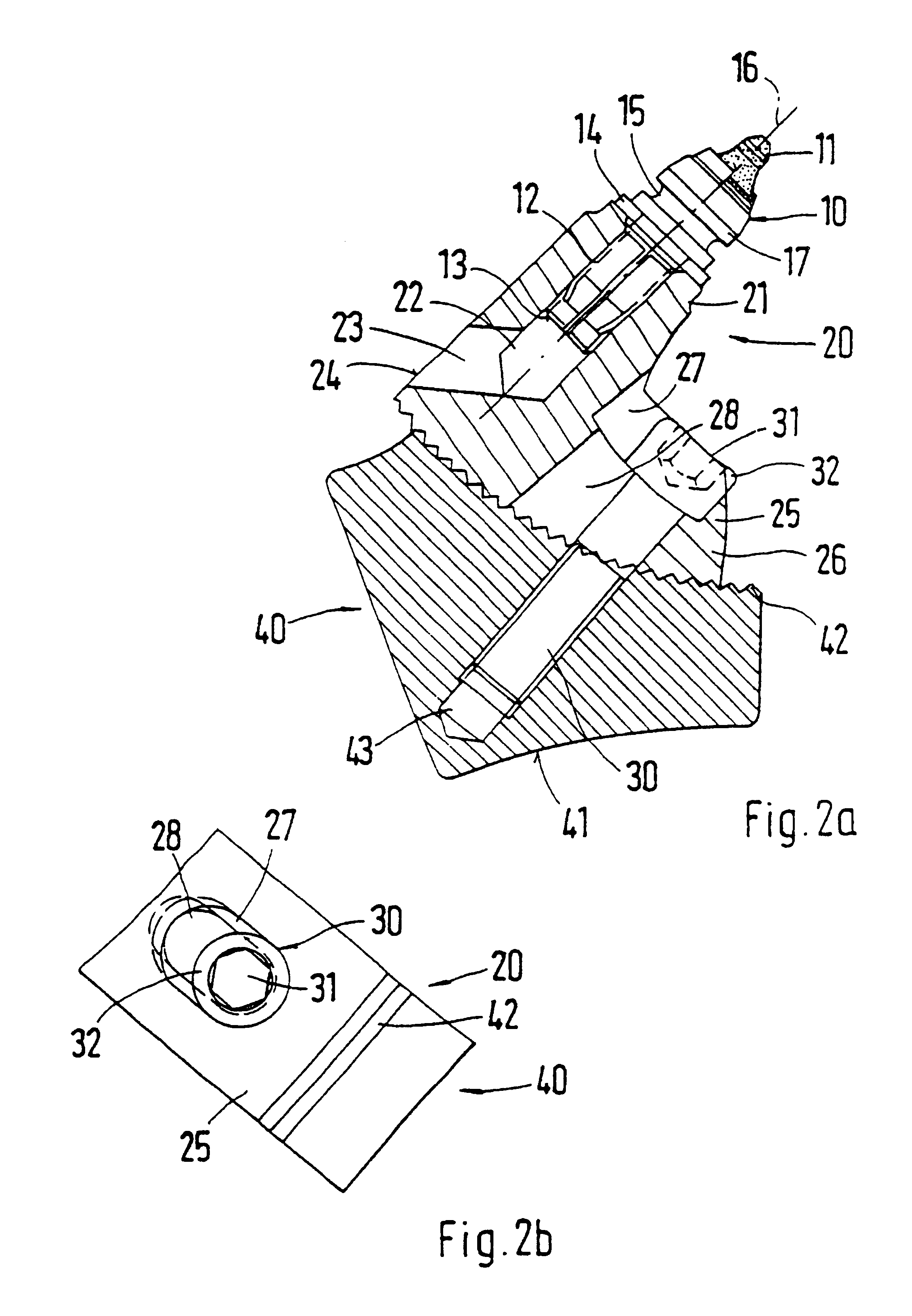
In order to create a fixed connection of the chisel holder to the base part, which simultaneously allows simple and quick changing of the working angle, in one embodiment of this invention the chisel holder has a base carrying a holder attachment for receiving the chisel. The base features an oblong hole that is aligned with a threading receiver of the base part. A fastening screw can be inserted into the oblong hole and the screw can be screwed into the threading receiver, and the chisel holder can be adjusted when the fastening screw is removed.
An especially good and quick attachment of the screw head to the chisel holder can be achieved if the screw head is designed as an oval-head screw head.

Problems solved by technology

Wear or excessive stress can damage a chisel holder.

Method used


Image

  • Chisel holder changing system
  • Chisel holder changing system
  • Chisel holder changing system

Examples


Embodiment Construction

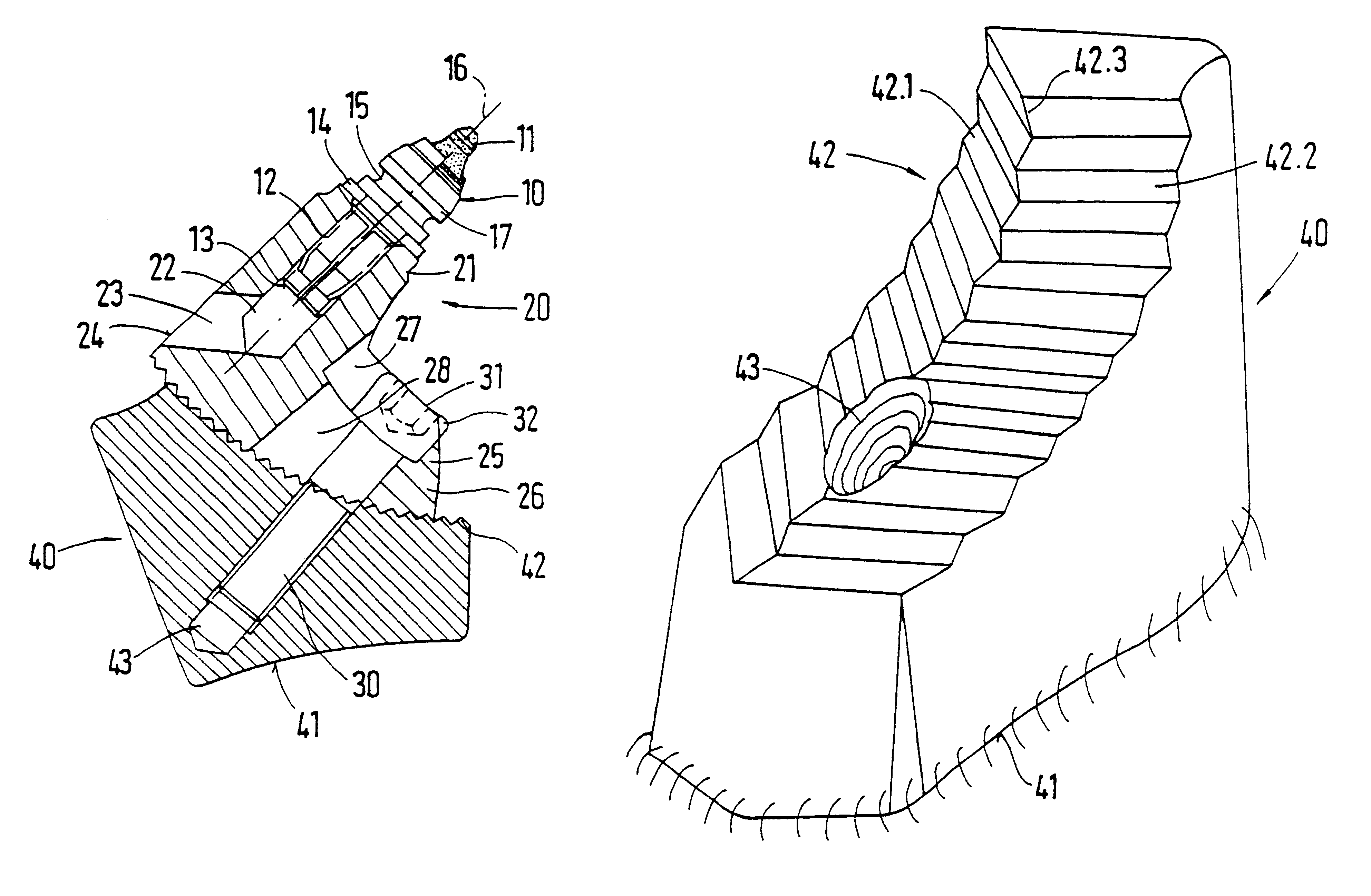
FIG. 1 shows a chisel-holder changing system that has a base part 40 and a chisel holder 20. The base part 40 has a lower connection surface 41, with which the base part 40 can be set on a roller-shaped base, for example, a road milling machine. The connection to the roller-shaped base is by welded joints. On its side facing upwards, the base part 40 has a curved contact surface. The contact surface has counter-toothing 42. The individual teeth of the counter-toothing 42 are designed with a triangular cross section, as shown in FIG. 1A, and thus form two contact edges. The teeth of the counter-toothing 42 extend over the entire width of the base part 40. A threaded receiver 43 is worked into the contact surface of the base part 40 at the center of the width of the teeth. In this way, the threaded receiver is arranged so that it occupies the greatest space possible in the base part 40 and therefore provides a sufficient thread length for a fastening screw. As shown in FIG. 1A, the th...


PUM


Abstract

A chisel-holder changing system for a road milling machine, a coal cutting machine or the like to which a chisel-holder is fastened in an exchangeable manner by means of a connecting mechanism. The chisel-holder accommodates at least one chisel that can be exchanged. The middle longitudinal axis of the chisel is set at an operating angle of less than 90° with respect to the surface to be worked. In order to be able to obtain varied removal results using such a chisel-holder changing system, the chisel-holder can be fixed in two or more configuring positions to the base part and in different attachment positions of the chisel, the middle longitudinal axis of the chisel is slanted at various working angles.

Description

1. Field of the InventionThis invention relates to a chisel-holder changing system for a road milling machine, a coal cutting machine, or the like, to which a chisel holder is fastened in an exchangeable manner by a connecting mechanism, wherein the chisel holder accommodates at least one chisel that can be exchanged, and wherein a central longitudinal axis of the chisel is set at a working angle of less than 90.degree. relative to the surface to be worked.2. Description of Related ArtA chisel-holder changing system is known from German Patent Reference DE 43 22 401 C2. The chisel-holder changing system features a base part that is welded onto a surface of a roller body that projects outwardly. The base part has a plug receiver, in which a plug connector of the chisel holder can be inserted. The chisel holder has a receiving hole, in which the chisel shaft of a circular-shaft chisel is inserted. The chisel holder can be fixed to the base part using a fastening screw. In the assemble...

Claims


Application Information

Patent Timeline
Patent Type & Authority Patents(United States)
IPC IPC(8): E21C35/18E21C35/19E21C35/193E21C35/00
CPCE21C35/18E21C35/19E21C35/193Y10T403/32262E21C2035/1826E21C2035/191E21C35/188E21C35/191
Inventor HOLL, BERNDSIMONS, DIETERHAHN, GUNTER
Owner WIRTGEN GMBH
Learn More