Toothed tool coupling for rotating a rotary tool

a technology of rotary tools and couplings, which is applied in the direction of manufacturing tools, branching pipes, mechanical apparatus, etc., can solve the problems of screw elongation and difficulty in defining the abutment between the ridges and grooves

Inactive Publication Date: 2003-09-23
SANDVIK INTELLECTUAL PROPERTY AB
View PDF9 Cites 48 Cited by
  • Summary
  • Abstract
  • Description
  • Claims
  • Application Information

AI Technical Summary

Benefits of technology

Another aim of the present invention is that also at a moderate axial pre-tension, there is an exceptionally small risk of failure of the transmission of torque.
An additional aim of the present invention is that the tool coupling is free of play.

Problems solved by technology

The high axial force may lead to an elongation of the screw.
Furthermore, it is difficult to define where abutment between the ridges and grooves will take place since the ridges and grooves have a linear extension.

Method used


Image

  • Toothed tool coupling for rotating a rotary tool
  • Toothed tool coupling for rotating a rotary tool
  • Toothed tool coupling for rotating a rotary tool

Examples


Embodiment Construction

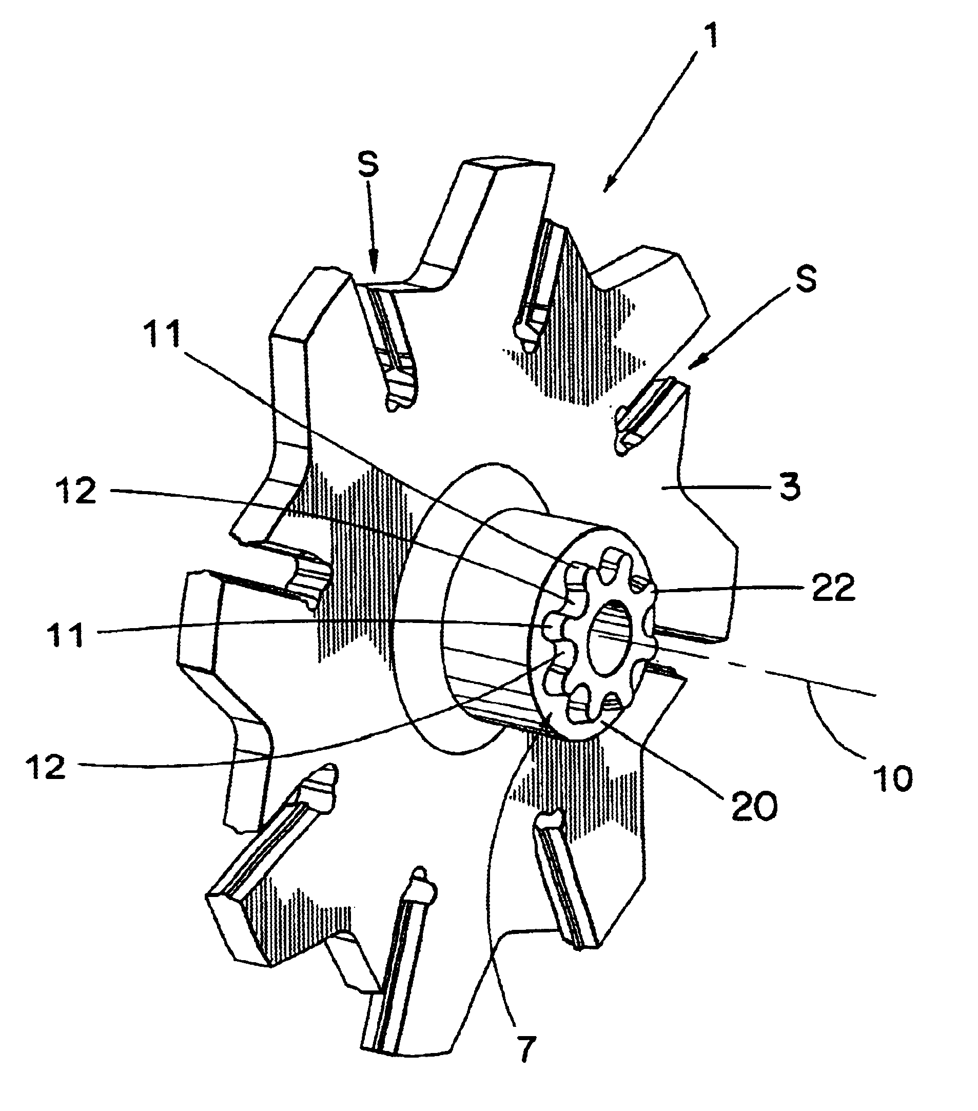
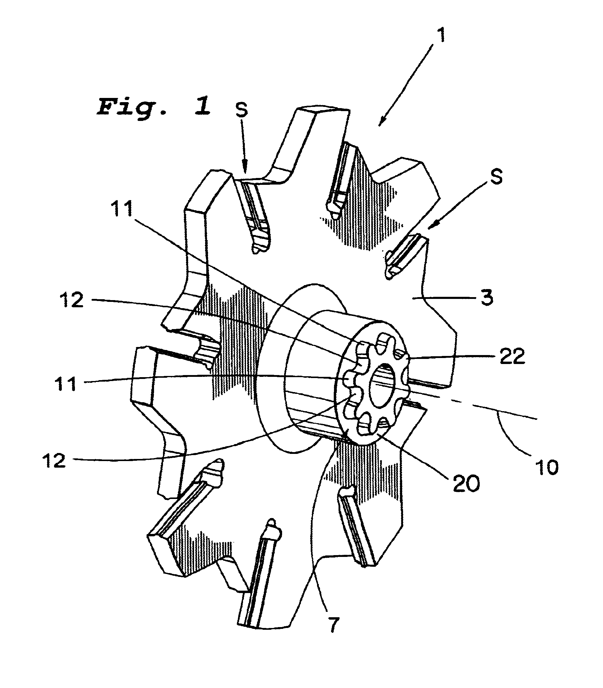
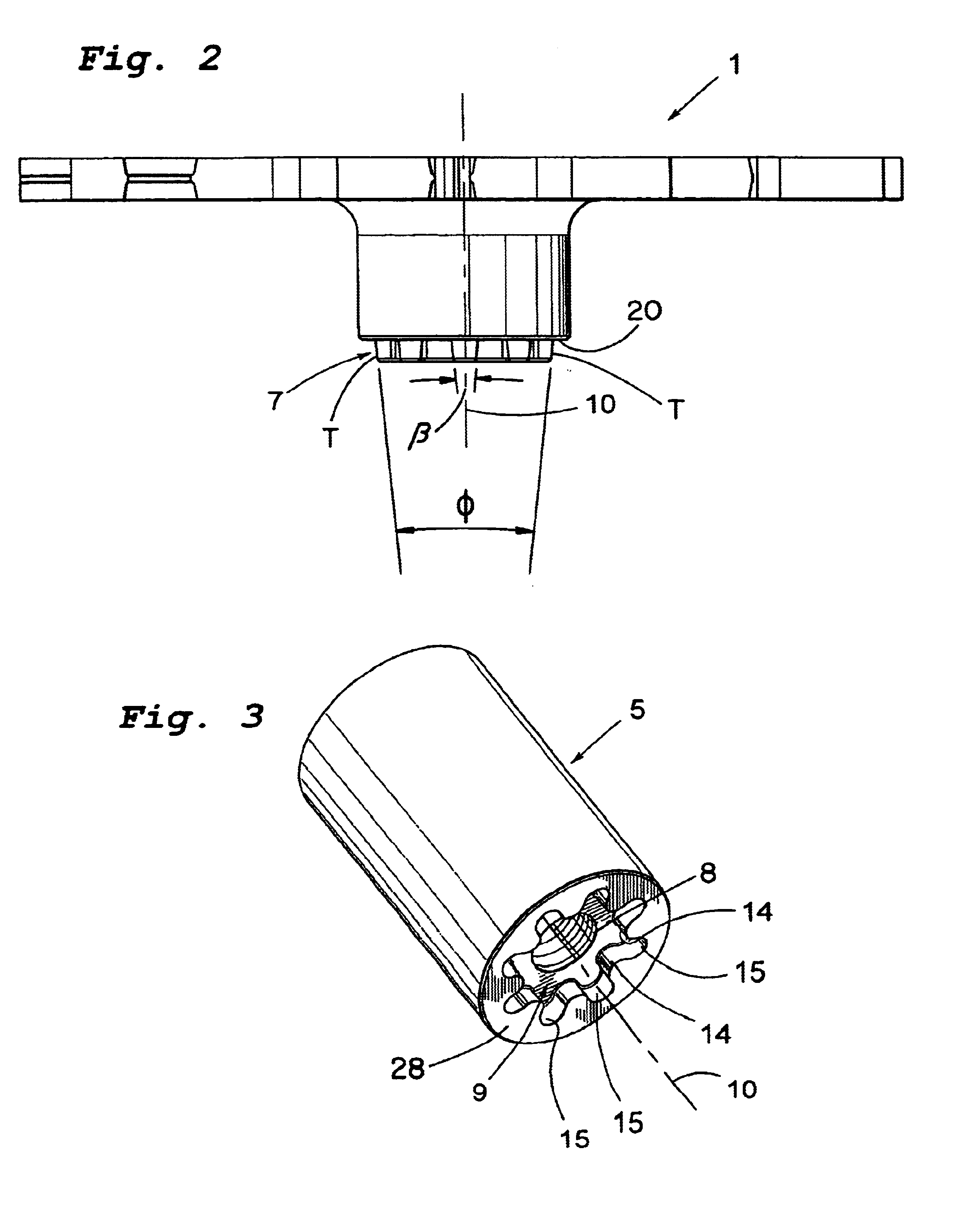
The tool coupling according to the present invention illustrated in FIGS. 1-5 is arranged in connection with a first rotary tool 1 in the form of a slitting cutter. The slitting cutter which comprises an adaptor in the form of a slitting cutter body 3 having seats S for receiving metal cutting inserts. The slitting cutter body 3 and a drive shaft 5 are interconnected by means of a tool coupling according to the present invention. Said tool coupling comprises a male driven part 7 and a female driven part 9, the male part 7 shaped to be received in the female part and to cooperate therewith for the transmission of torque between the shaft 5 and the slitting cutter body 3. The parts 7, 9 have a common axis of rotation 10.

The male part 7, which is most clearly seen in FIG. 1, is disposed on an axially facing end surface 20 of the tool 1 and comprises a number of driven teeth 11, which are circumferentially spaced-apart from each other, and which form a tangent to an imaginary circle hav...


PUM


Abstract

A driven tool includes a driven part which is rotatably driven by a drive part. The driven part and the drive part are coaxially arranged one inside of the other. The drive part and the driven part are conical as viewed in a longitudinal section plane containing the axis. The driven part includes driven teeth projecting generally radially with respect to the axis and received in respective radially-open recesses formed in the drive part. Each of the driven teeth makes contact with a wall of the respective recess at first and second contact places which are respectively situated on opposite sides of a generally radial line of symmetry of the driven tooth. The contact places are operable to transmit a drive force from the drive part to the driven part in respective directions of rotation. A driving angle in the range of -5° to +45° is formed at each contact place.

Description

This application is based on and claims priority under 35 U.S.C. .sctn.119 with respect to Sweden Application No. 0001825-9 filed on May 18, 2000, the entire content of which is incorporated herein by reference.The present invention relates to a tool coupling, preferably for rotary tools, intended to rotate around an axis of rotation. The tool coupling serves to couple together a drive member and a tool body intended to carry cutting inserts for chip removing machining. The tool coupling comprises a toothed male part and a toothed female part, which parts are intended to be received one in the other.PRIOR ARTA coupling element which can be coupled together with another member for the transmission of a rotation movement therebetween, wherein said coupling element may consist of a screw head, for example, is previously known from U.S. Pat. No. 3,584,667.The coupling element according to U.S. Pat. No. 3,584,667 comprises a first series of spaced-apart, partially cylindrical convex surf...

Claims


Application Information

Patent Timeline
Patent Type & Authority Patents(United States)
IPC IPC(8): B23B31/10B23B31/11B23B31/00B23C5/00
CPCB23B31/008B23B31/11Y10T403/4688Y10T403/7035Y10T403/7026Y10T403/4677Y10T403/7031Y10T82/2591F16B2200/40F16B2200/406
Inventor HANSSON, PERSJOO, STURE
Owner SANDVIK INTELLECTUAL PROPERTY AB
Why Eureka
Try Eureka