
Circuit-breaker including a channel for emptying the piston-driven compression chamber

a circuit-breaker and compression chamber technology, applied in the field of circuit-breakers, can solve the problems of circuit-breaker opening operation to be stopped undesired, electric arc might develop,

Inactive Publication Date: 2003-09-23
ALSTOM TECH LTD
View PDF7 Cites 8 Cited by
  • Summary
  • Abstract
  • Description
  • Claims
  • Application Information

AI Technical Summary

Benefits of technology

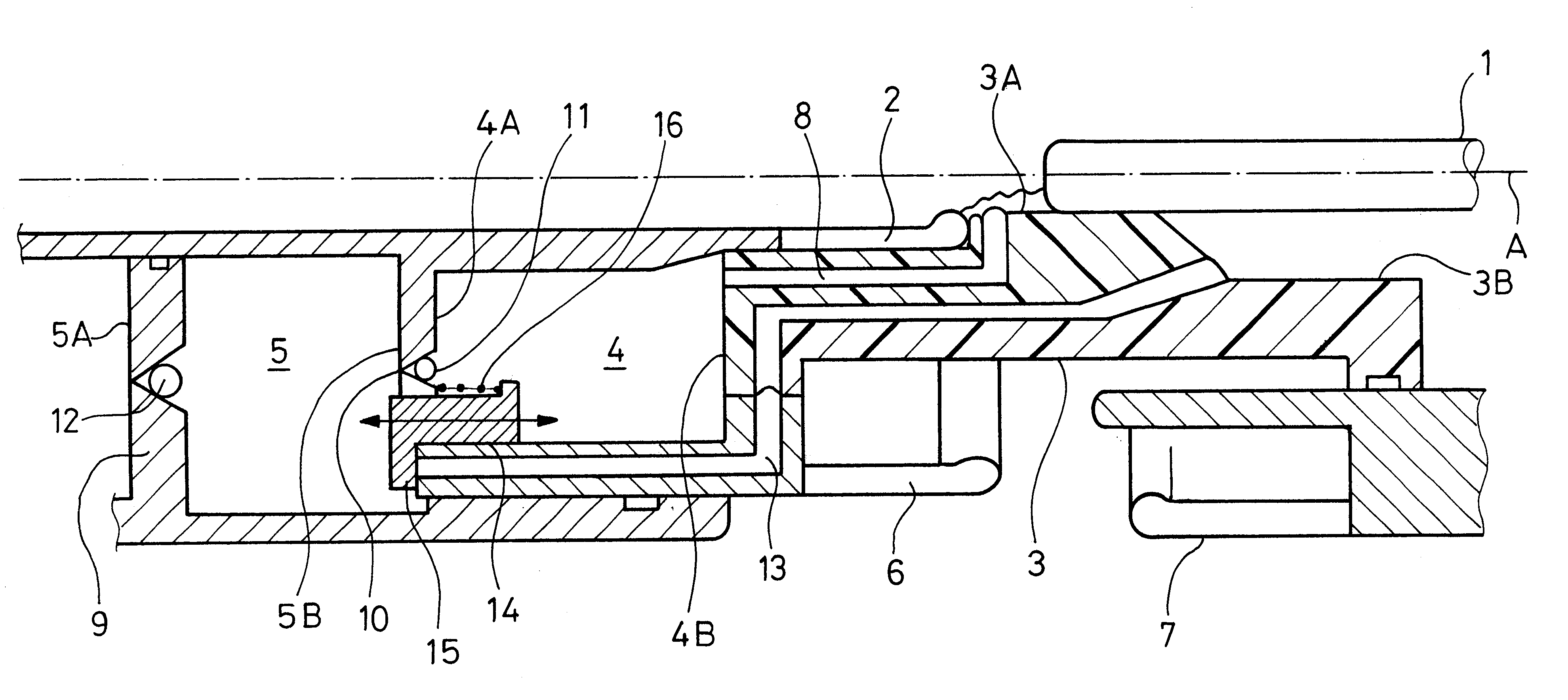
An object of the invention, is to provide a circuit-breaker that does not suffer from the above-mentioned drawbacks. In particular, an object of the invention is to provide a circuit-breaker in which, when interrupting low current, all of the gas under increased pressure in the piston-driven compression chamber goes through the thermal blast chamber to blast the electric arc that strikes between the two contacts of the circuit-breaker, and in which, when interrupting high current, the piston-driven compression chamber is emptied fully without using calibrated valves in the compression piston, but rather by discharging the gas into the interrupting space via a separate discharge channel, this injection of non-ionized or little-ionized gas contributing to regenerating the hot gases present in the interrupting space so as to improve the dielectric strength of the circuit-breaker during subsequent opening thereof.
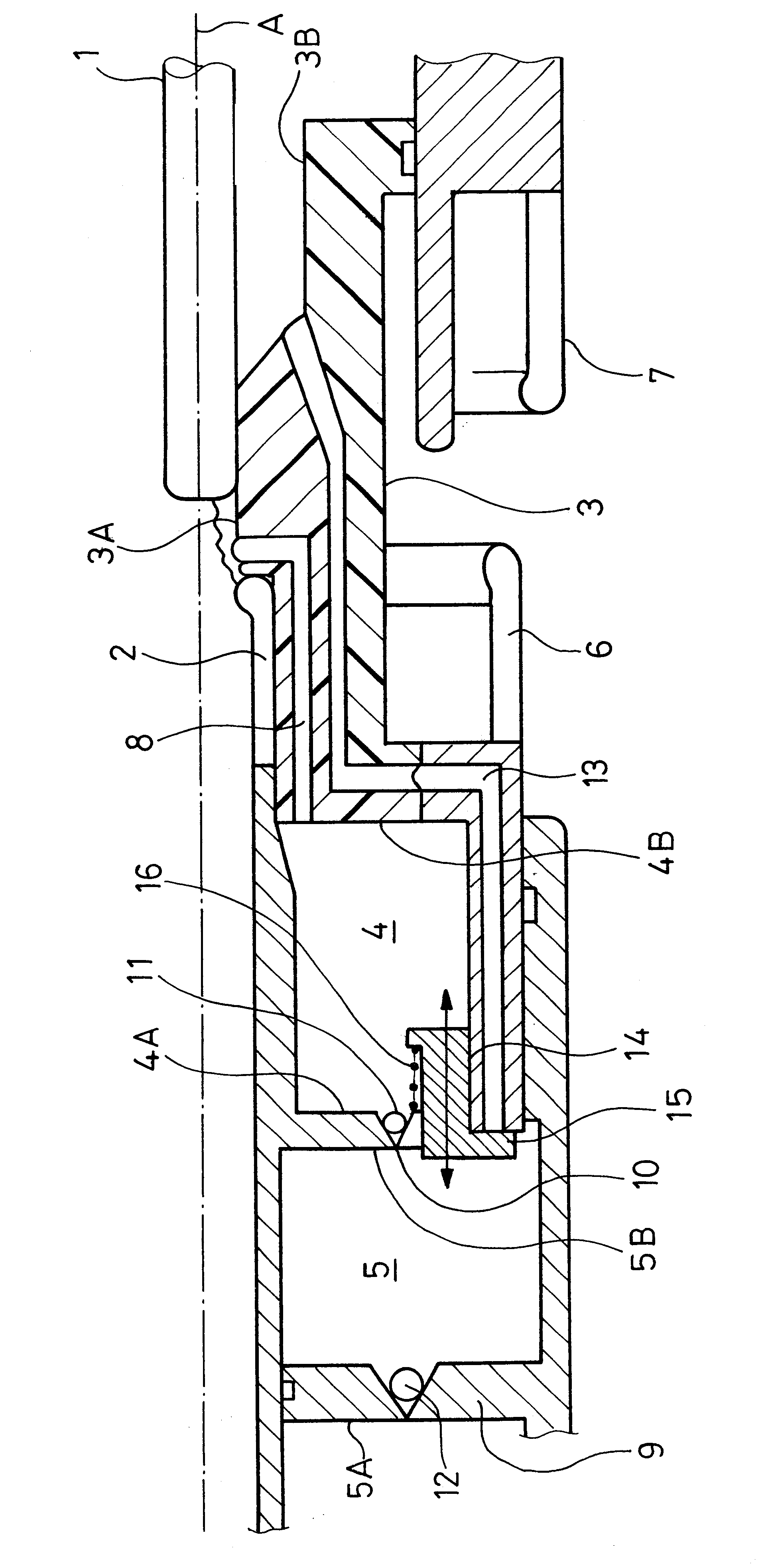
In a particularly simple embodiment of the circuit-breaker of the invention, the discharge valve is a moving ring that passes through the bottom of the thermal blast chamber and through the top of the piston-driven compression chamber, and the discharge channel has an opening via which it opens out in the top of the piston-driven compression chamber. The ring is pressed against the opening in the discharge channel under the action of a return spring that works between the ring and the bottom of the thermal blast chamber. With this configuration, when the pressures in the thermal blast chamber and in the piston-driven compression chamber are equal, the ring closes off the discharge channel and prevents the piston-driven compression chamber from emptying towards the interrupting space.
In another particular embodiment of the circuit-breaker of the invention, the interrupting space is defined by a nozzle that has a diverging portion, and the discharge channel opens into the diverging portion downstream from the neck of the nozzle. This construction removes the risk of the discharge channel being blocked by the electric arc.

Problems solved by technology

Unfortunately, a portion of the gas under increased pressure in the piston-driven compression chamber is also discharged into the interrupting space through the discharge channel.
When the fixed contact uncovers the mouth of the discharge channel in the neck in the nozzle, there is a risk that the electric arc might develop at the mouth of the discharge channel because of the small diameter of the neck of the nozzle, and, by heating the gases, might cause them to return from the interrupting space towards the piston-driven compression chamber.
Although such return is stopped by the check valve of the discharge channel, the piston-driven compression chamber can then no longer be emptied, and the increase in the pressure of the gas in said chamber causes an opposing force that opposes the movement of the moving contact of the circuit-breaker, and can cause the circuit-breaker opening operation to be stopped undesirably.
In that way, when interrupting high current, the piston-driven compression chamber is emptied via the rear of the piston, but the gas under increased pressure in said chamber is then not used for interrupting the arc, and it is therefore lost.

Method used


Image

  • Circuit-breaker including a channel for emptying the piston-driven compression chamber
  • Circuit-breaker including a channel for emptying the piston-driven compression chamber

Examples


Embodiment Construction

The FIGURE is a diagrammatic axial half-section view showing an embodiment of a high-voltage circuit-breaker of the invention. The circuit-breaker includes a fixed arcing contact 1 in the form of a rod, and a moving arcing contact 2 which moves axially along the axis A. The contact 2 is hollow and is part of moving equipment including a blast nozzle 3 that is coaxial with the contacts 1 and 2, a thermal blast chamber 4, and a piston-driven compression chamber 5. The moving equipment also includes a permanent current contact 6 which, when the circuit-breaker is closed, co-operates with a permanent current contact 7 that is fixed.

The nozzle 3 is made of an electrically-insulating material, and it has a diverging portion 3B downstream from its neck 3A which is of smaller section. When the circuit-breaker is closed, the arcing contact 1 passes through the neck 3A of the nozzle and penetrates into the hollow contact 2 which is disposed upstream from the neck 3A of the nozzle, relative to...


PUM


Abstract

A circuit-breaker includes two contacts which are disposed in an interrupting space filled with a dielectric gas under pressure and between which an electric arc strikes during circuit-breaker opening, a thermal blast chamber communicating directly with the interrupting space, and a piston-driven compression chamber communicating with the thermal blast chamber. The piston-driven compression chamber communicates with the interrupting space via a discharge channel that is separate from the thermal blast chamber and that is closed by a discharge valve. The discharge valve is disposed between the thermal blast chamber and the piston-driven compression chamber in a manner such that the discharge valve opens to enable the gas under increased pressure in the piston-driven compression chamber to be discharged towards the interrupting space via the channel when the increase in the pressure of the gases in the thermal blast chamber is larger than the increase in the pressure of the gases in the piston-driven compression chamber.

Description

The invention relates to a circuit-breaker including two contacts which are disposed in an interrupting space filled with a dielectric gas under pressure and between which an electric arc strikes during circuit-breaker opening, the circuit-breaker further including a thermal blast chamber that communicates directly with the interrupting space, and a piston-driven compression chamber that communicates with the thermal blast chamber, in which circuit-breaker the piston-driven compression chamber communicates with the interrupting space via a discharge channel that is separate from the thermal blast chamber and that is closed by a discharge valve.Such a high-voltage circuit-breaker is known from German Patent DE-19613030. In that known circuit-breaker, the interrupting space is defined by the neck and the diverging portion of a nozzle secured to the moving contact of the circuit-breaker. When the circuit-breaker is in the closed position, the fixed contact of the circuit-breaker passes...

Claims


Application Information

Patent Timeline
Patent Type & Authority Patents(United States)
IPC IPC(8): H01H33/90H01H33/88
CPCH01H33/901
Inventor DUFOURNET, DENISGRIESHABER, WOLFGANGPERRET, MICHEL
Owner ALSTOM TECH LTD
Learn More