

Method of reducing intensity distortion induced by cross phase modulation in a WDM optical fiber transmission system
a technology of cross-phase modulation and transmission system, which is applied in the direction of multiplex communication, cladded optical fibre, instruments, etc., can solve the problems of limiting the maximum power that can be introduced into the transmission optical fiber, gvd distortion, propagation limit of wdm, etc., and achieves the effect of reducing intensity distortion and reducing various drawbacks
- Summary
- Abstract
- Description
- Claims
- Application Information
AI Technical Summary
Benefits of technology
Problems solved by technology
Method used
Image

Examples
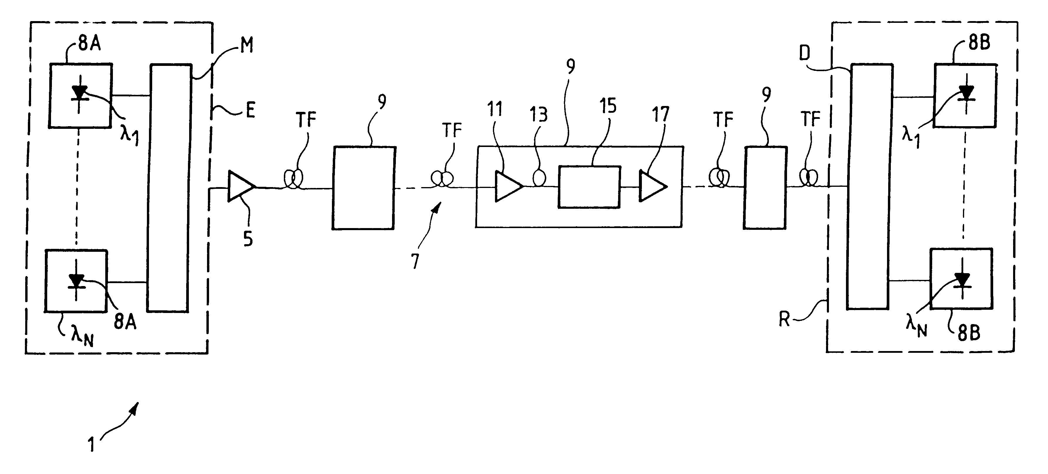
first embodiment
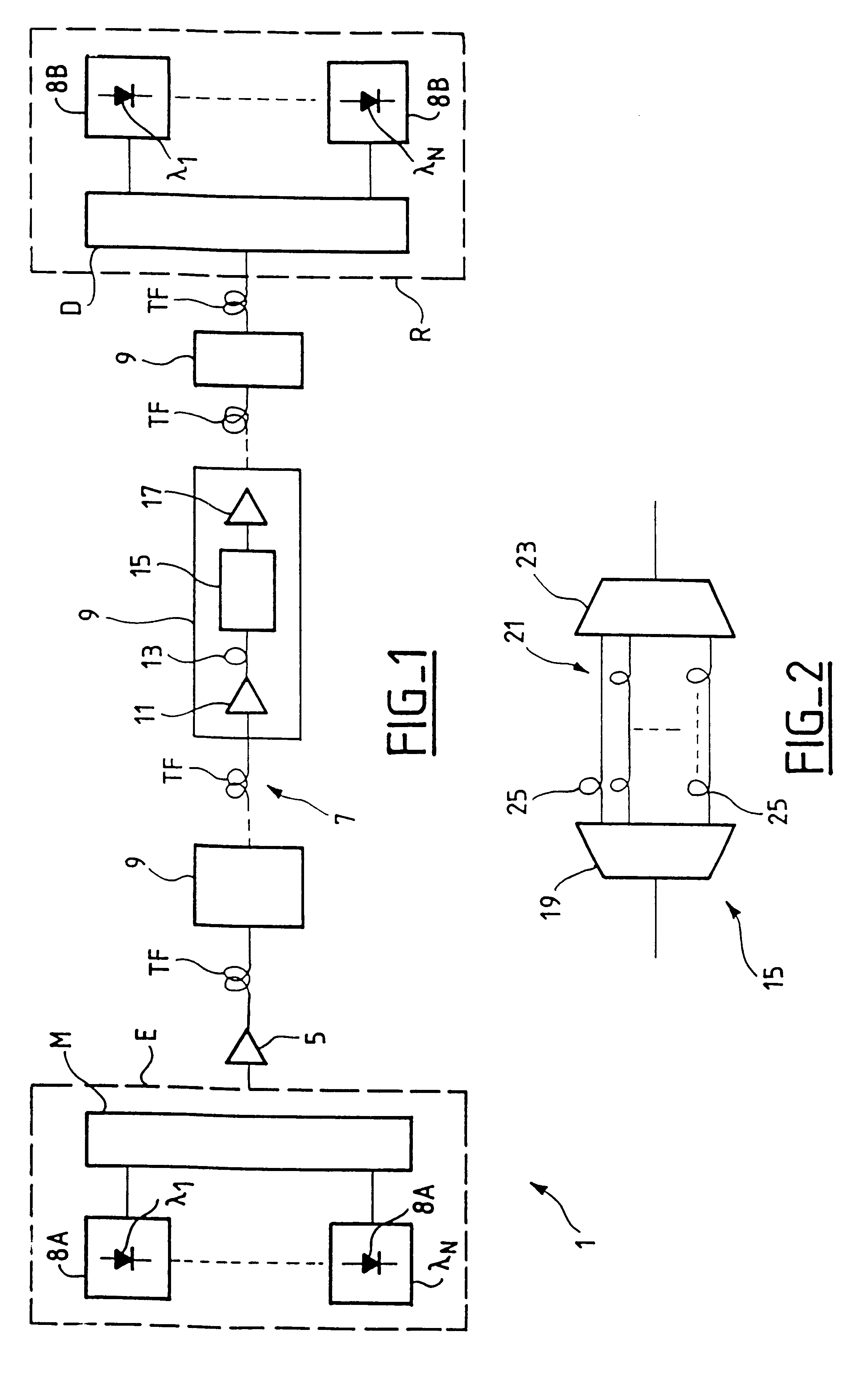
Reference is now made to FIG. 2 which is a more detailed block diagram of the unit 15.
As can be seen in FIG. 2, the unit 15 comprises a demultiplexer 19 having one inlet and nine outlets, a set of N parallel optical fiber lines corresponding to the N transmission channels, and a multiplexer 23 having N inlets and one outlet.
Each optical fiber line includes an optical delay line 25 introducing relative delays between the channels such that the (n+1).sup.th and the n.sup.th channel at the input to the optical fiber segment TF following the unit 15 are offset by .tau..sub.n relative to their positions in the fiber segment TF preceding the unit 15.
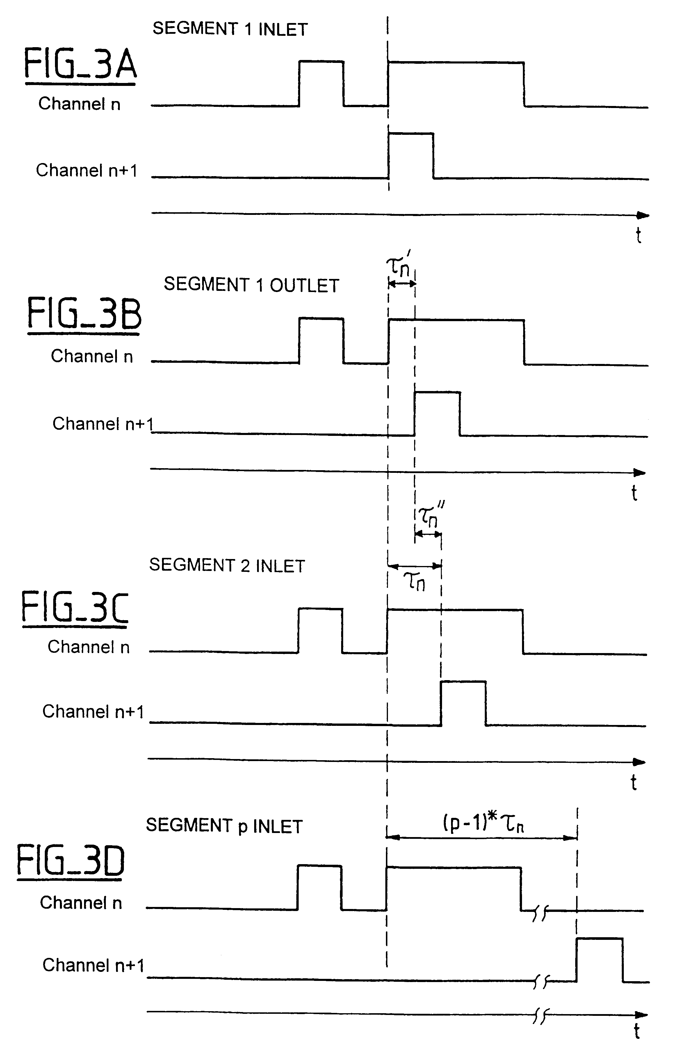
By way of example, FIGS. 3A, 3B, 3C, and 3D show the time offsets of two transmitted bit sequences respectively on the channel n and on the channel n+1 at different locations in the transmission system 1.
Thus, it can be seen in FIG. 3A that the bit sequence on channel n is: 10111, and the sequence on channel n+1 is: 00100. To show the principl...
PUM
 Abstract
Description
Claims
Application Information