
Optical component of the waveguide array spectrograph type, having centered outlet channels

a waveguide array and optical component technology, applied in the direction of optical elements, transmission monitoring, instruments, etc., can solve the problems of not enabling a single optical fiber to receive and emit telephone signals, not enabling both-way communication, and unable to perform only one system, so as to achieve the effect of convenient visualization

Inactive Publication Date: 2001-09-11
FRANCE TELECOM SA
View PDF3 Cites 5 Cited by
  • Summary
  • Abstract
  • Description
  • Claims
  • Application Information

AI Technical Summary

Benefits of technology

An object of the present invention is to mitigate those various drawbacks.
A second object of the present invention is to provide a system that is simple to make, and that is suitable for simultaneously performing those various operations at one end of an optical fiber.
FIG. 13 is a plot similar to FIG. 12 in which the various portions of the plot, each corresponding to a single outlet channel, are brought together to make the plot easier to visualize;

Problems solved by technology

The various systems mentioned above also suffer from the drawback of performing only one of the three above-mentioned operations that may be necessary at one end of an optical fiber.
Thus, at a given end of the fiber, they do not enable both-way communication to be provided simultaneously with wavelength separation of incoming signals, or both-way communication with multiplexing of signals to be injected into the fiber.
For example, the simple systems that have been proposed in the past do not enable a single optical fiber to receive and emit telephone signals while simultaneously receiving a television signal.

Method used


Image

  • Optical component of the waveguide array spectrograph type, having centered outlet channels
  • Optical component of the waveguide array spectrograph type, having centered outlet channels
  • Optical component of the waveguide array spectrograph type, having centered outlet channels

Examples


Embodiment Construction

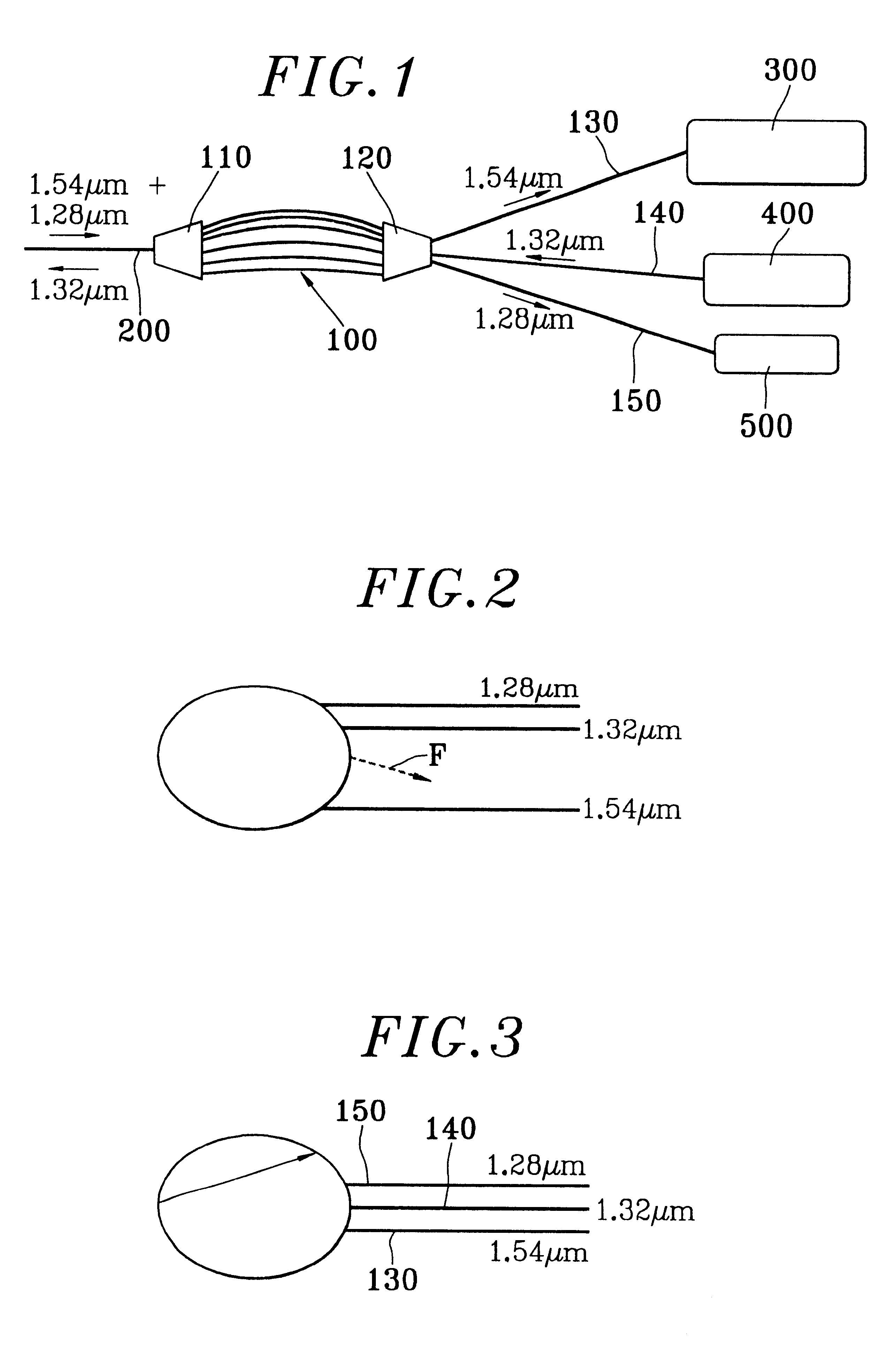
FIG. 1 is an overall view of an optical communications system of the invention. The central portion of FIG. 1 shows a phasar 100. The phasar has an inlet coupler 110 connected to an optical fiber 200.

By way of example, the optical fiber 200 is connected to a local optical telecommunications network, with the overall system of FIG. 1 being located in a dwelling. The FIG. 1 system is connected via the local network, for example, to a telephone exchange, to a center for broadcasting television signals, or indeed to computers situated in other dwellings.

Thus, the fiber 200 is designed to have optical signals travelling simultaneously therealong in opposite directions.

The phasar 100 has a second coupler 120. The coupler 120 has three channels going out from the phasar.

A first channel 130 connects the coupler 120 to a multichannel receiver 300. The receiver 300 is adapted to receive signals at wavelengths close to 1.54 .mu.m.

A second channel 140 connects the coupler 120 to an optical sign...


PUM


Abstract

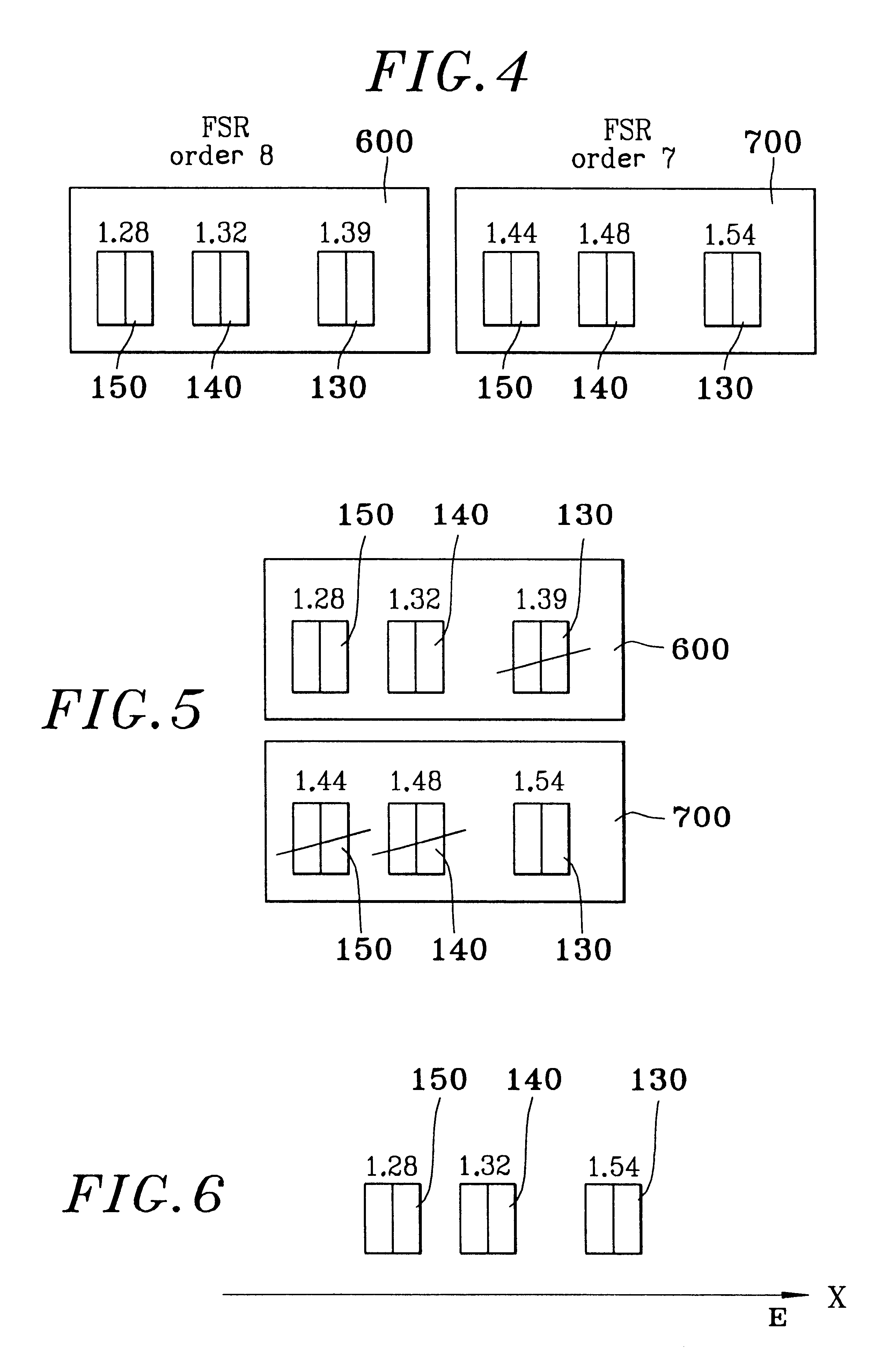
The present invention relates to an optical component of the waveguide array spectrograph type, the component comprising an inlet coupler and an outlet coupler between which said array extends, and including optical channels constituting inlets and outlets for the inlet and outlet couplers, the component being suitable for multiplexing and / or demultiplexing two optical signals of different wavelengths conveyed by two channels of the same coupler, wherein the waveguides of the array have lengths that are distributed in such a manner that two spectrum ranges of different center wavelengths both occur in said same coupler, said different wavelengths that are conveyed by the two channels each belonging to a different one of the free spectrum ranges.

Description

The present invention relates to multiplexer and / or demultiplexer optical components of the waveguide array spectrograph type, also known as "phasars".There is a desire at present to make use of optical fibers in ever more numerous and varied applications. Thus, it is desired to be able to use a single optical fiber to convey signals of different kinds, such as telephone signals, television signals, or indeed computer data.In conventional manner, the signals of different kinds conveyed in the same fiber are given different respective wavelengths specific to each signal, so as to enable the signals to be distinguished from one another.Thus, it is necessary to be able to use a single optical fiber to convey multiple signals simultaneously, including signals propagating in opposite directions, and it is thus necessary to be able to perform various different operations at an end of the optical fiber.A first operation is controlling both-way communications over an optical fiber, such as ...

Claims


Application Information

Patent Timeline
IPC IPC(8): G02B6/34G02B6/42
CPCG02B6/12011G02B6/12019G02B6/12014G02B6/4246
Inventor BRUNO, ADRIENWIN, PASCALRIGNY, ARNAUD
Owner FRANCE TELECOM SA
Learn More