Device in a level gauging system

a level gauge and device technology, applied in the direction of liquid/fluent solid measurement, engine lubrication, antennas, etc., can solve the problems of dispersed radar wave propagation and/or absorbed radar wave, and the appearance of condensed fluid

Inactive Publication Date: 2003-10-07
ROSEMOUNT TANK RADAR
View PDF6 Cites 40 Cited by
  • Summary
  • Abstract
  • Description
  • Claims
  • Application Information

AI Technical Summary

Problems solved by technology

Condensed fluid on the antenna surface leads to disturbed propagation of the radar waves and/or absorbed radar waves.
Antennas provided with a radome placed at a distance from the antenna leaving a space filled with air between t

Method used


Image

  • Device in a level gauging system
  • Device in a level gauging system
  • Device in a level gauging system

Examples


Embodiment Construction

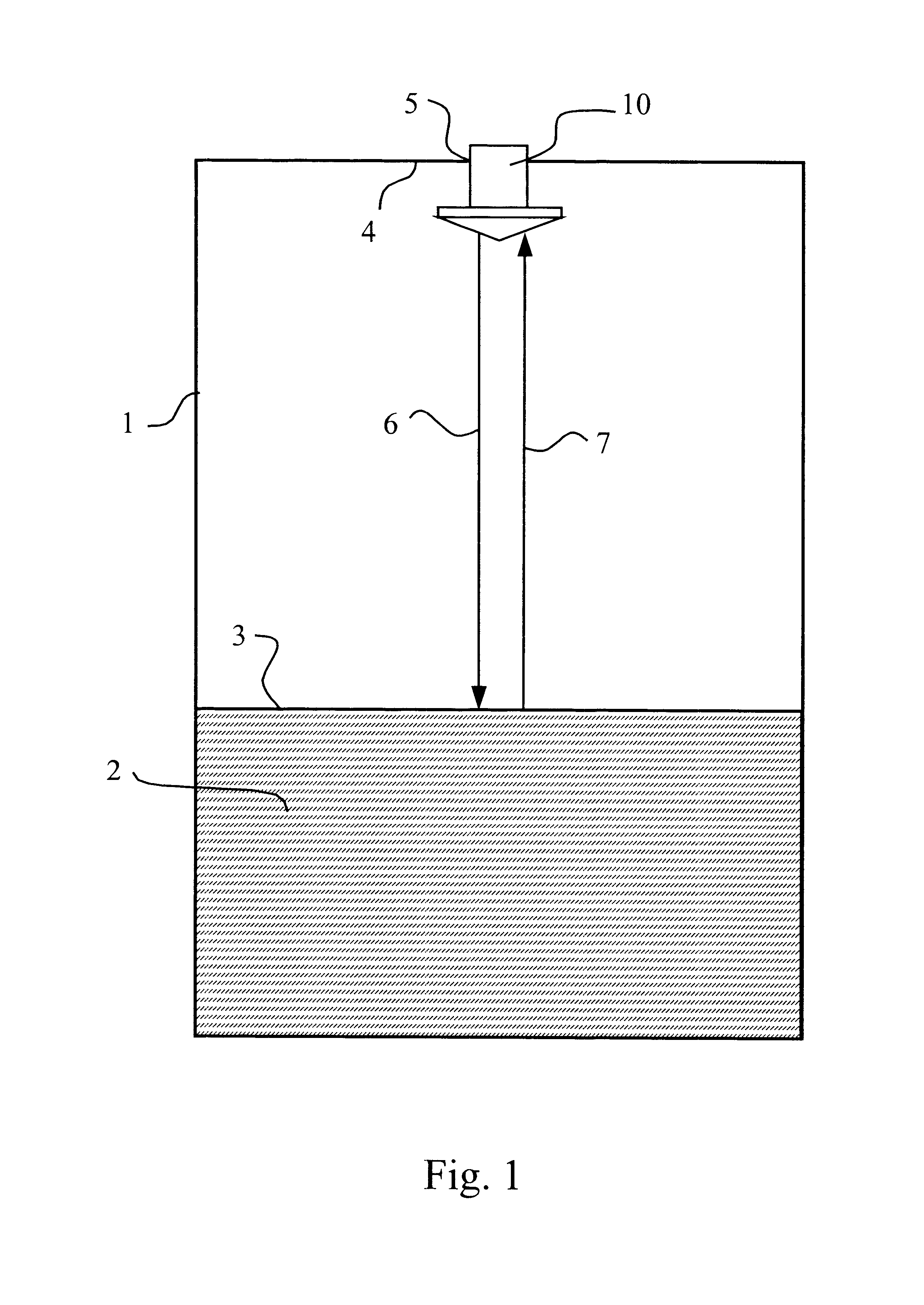
FIG. 1 shows a fluid level gauging system using radar waves for measuring the fluid level in a container 1. The container 1 contains a fluid 2 and can e.g. be a tank on a ship, in a process industry or a tank in an oil refinery. The fluid may be a liquid such as oil, a gas or pulverized solid material such as sand or stone powder. The system comprises a planar antenna 10 which is mounted in an opening 5 in a lid 4 of the container 1. The antenna 10 is directed against a fluid surface 3 and arranged to transmit radar waves towards the fluid surface 3, denoted with arrow 6, and to receive reflected radar waves from the fluid surface 3, denoted with arrow 7. The system further comprises a radar unit (not shown) in which the radar waves are generated

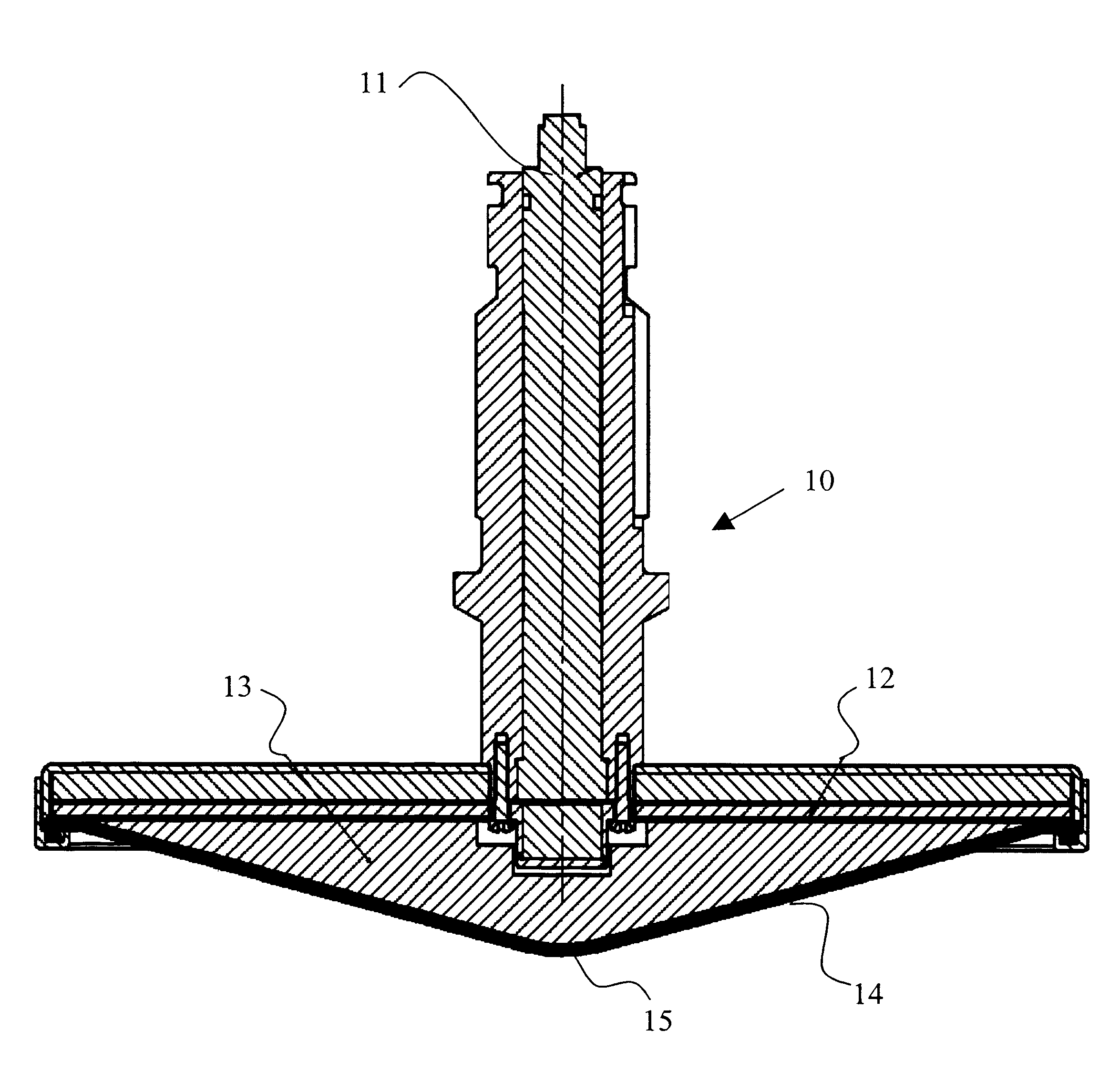
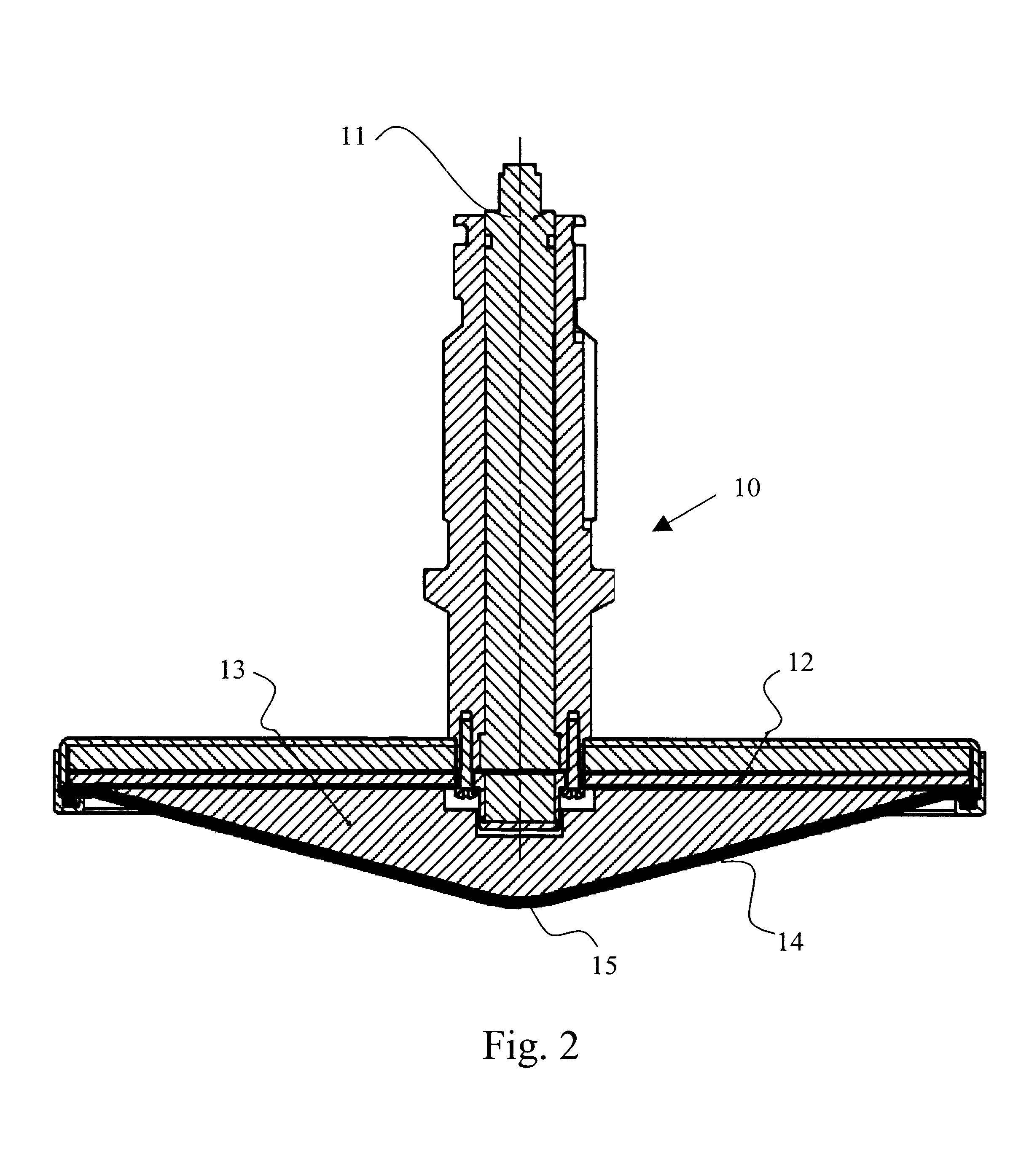
Referring now to FIG. 2, the antenna 10 comprises a transmission line 11 and a plane surface 12. Planar antennas are well-known in the art and are not described in detail herein, see for example "Microstrip Antenna Design Handbook" by R. Gar...


PUM


Abstract

The present invention relates to a device in a level gauging system comprising an antenna using radar waves to gauge a level of a surface of a fluid kept in a container. The antenna is arranged above the fluid surface and comprises a plane surface facing the fluid surface and being substantially parallel with the fluid surface. The plane surface has means for transmitting radar waves towards the fluid surface and means for receiving reflected radar waves from the fluid surface in order to gauge the fluid level. The antenna comprises a radome which at least partially covers the plane surface and is shaped such that condensed fluid is directed away from the antenna by force of gravity. A thermally insulating filling material is provided between the radome and the plane surface.

Description

The present invention relates generally to an antenna using radar waves in a level gauging system and, more particularly, to an antenna comprising a plane surface from which radar waves are transmitted towards a surface of a fluid kept in a container and to which reflected radar waves are received from the fluid surface in order to gauge the fluid level in the container.DESCRIPTION OF THE RELATED ARTIn level gauging systems using radar waves for gauging the fluid level in a container, such as a tank on a ship or the like, planar antennas are commonly used today since they are fairly cheap to manufacture. These antennas are usually mounted in an opening in the lid of the container and comprise a plane surface facing the surface of the fluid and having means for transmitting / receiving radar waves in order to gauge the fluid level. The plane surface of the antenna forms a horizontal cold wall which causes e.g. water vapour to condensate on the plane surface, especially if the container...

Claims


Application Information

Patent Timeline
IPC IPC(8): G01F23/284H01Q1/40H01Q1/00H01Q1/22H01Q1/42
CPCG01F23/284H01Q1/22H01Q1/42H01Q1/40H01Q1/225
Inventor WESTERLING, JANH.ANG.KANSSON, MAGNUS
Owner ROSEMOUNT TANK RADAR
Why Eureka
Try Eureka