System and method for redirecting a signal using phase conjugation

Inactive Publication Date: 2003-10-07
RAYTHEON CO
View PDF4 Cites 43 Cited by
  • Summary
  • Abstract
  • Description
  • Claims
  • Application Information

AI Technical Summary

Problems solved by technology

This approach can be problematic inasmuch as it requires the steering of a physical antenna and is therefore relatively computationally intensive, slow and costly.
Thus, whi

Method used


Image

  • System and method for redirecting a signal using phase conjugation
  • System and method for redirecting a signal using phase conjugation
  • System and method for redirecting a signal using phase conjugation

Examples


Embodiment Construction

Illustrative embodiments and exemplary applications will now be described with reference to the accompanying drawings to disclose the advantageous teachings of the present invention.

While the present invention is described herein with reference to illustrative embodiments for particular applications, it should be understood that the invention is not limited thereto. Those having ordinary skill in the art and access to the teachings provided herein will recognize additional modifications, applications, and embodiments within the scope thereof and additional fields in which the present invention would be of significant utility.

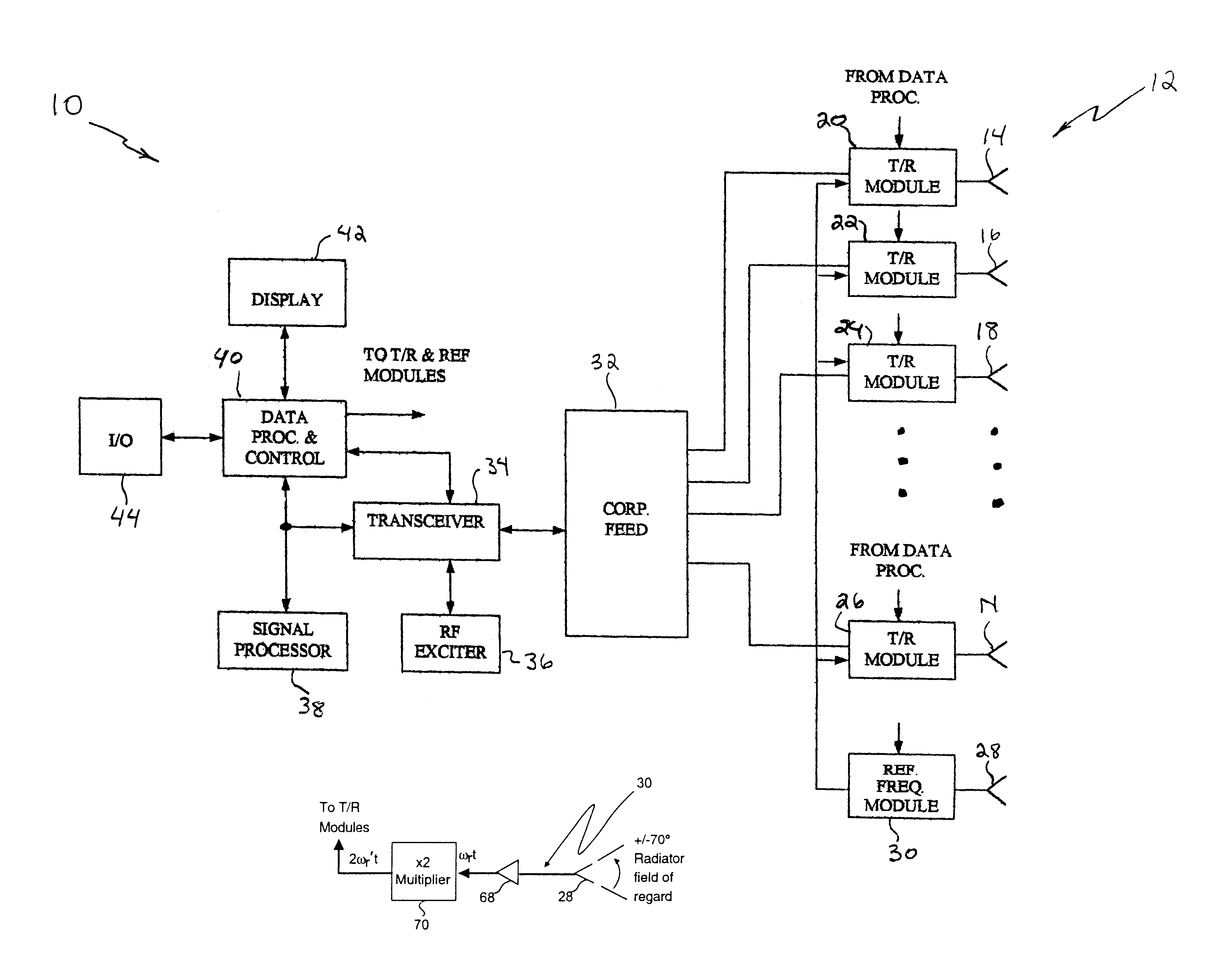
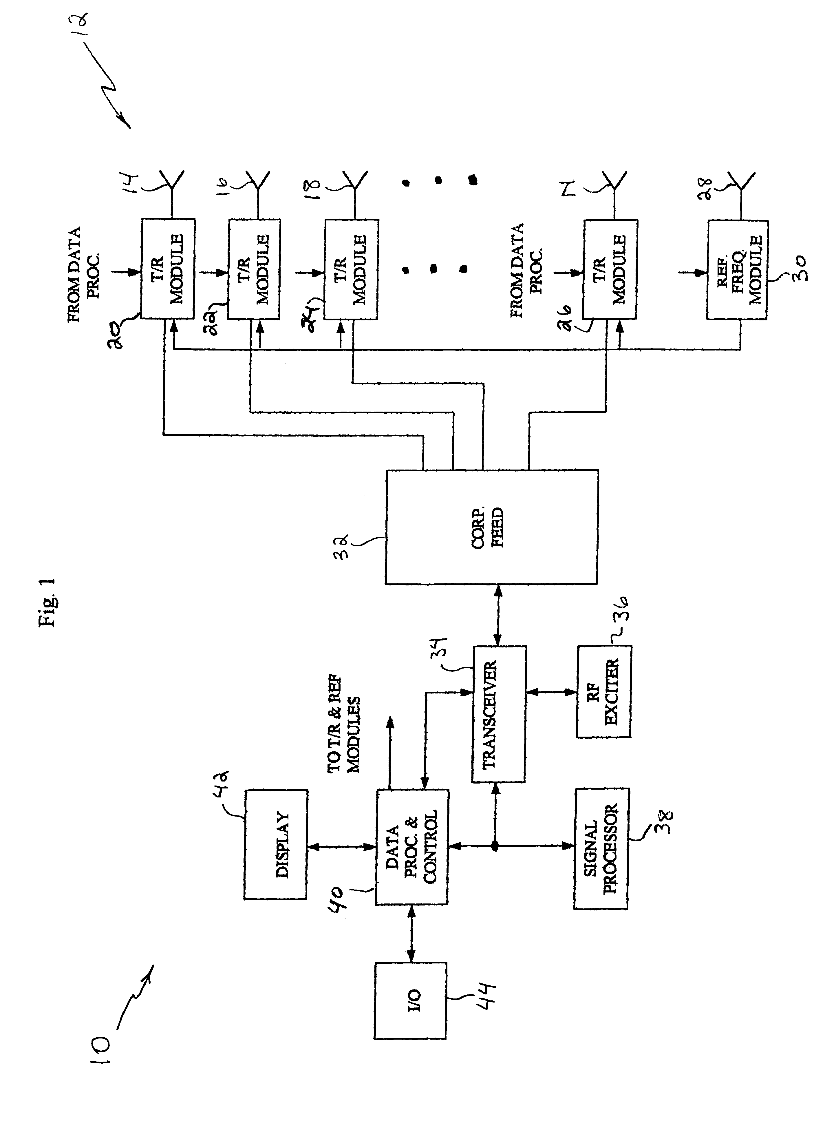
FIG. 1 is a block diagram of an illustrative embodiment of an RF radar or communications system implemented in accordance with the teachings of the present invention. The system 10 includes a phased array antenna 12 adapted to transmit and receive radio frequency (RF) signals via a plurality of radiating elements 14, 16, 18 . . . N and 28 connected to a number o...


PUM


Abstract

A system and method for automatically generating a return beam in the direction of a received beam. The inventive system (10) includes a phased array antenna (12) for receiving a radio frequency signal having a first wavefront from a first direction. In response to this signal, the invention (10) provides a second signal having a second wavefront. The second signal is a phase conjugate of the first signal and is transmitted in a reverse direction relative to the direction of the first signal. In the illustrative embodiment, the invention includes a plurality of phase conjugators each of which are disposed in a transmit/receive module and coupled to an associated radiating element. Each of the phase conjugators includes a mixer (60) having the input signal as a first input thereto. The input signal has a first frequency and a first phase. A second signal having a frequency equal to twice the first frequency is input to each mixer (60) from a reference frequency module (30) such that the output of the mixer includes a component representative of the negative of the first phase. The output of each mixer (60) is filtered to extract a signal component having a negative phase relative to the input signal. These signal components are then transmitted as the phase conjugated wavefront. This process will occur for each signal when multiple signals are received within the field of regard of the phased array antenna (12).

Description

1. Field of InventionThe present invention relates to RF systems. More specifically, the present invention relates to phased array antenna systems used for RF systems and other applications.2. Description of the Related ArtFor many applications, it is necessary or desirable to be able to automatically track a received signal. In a radar or communication application, for example, it might be useful to be able to track a source of a received signal. A satellite or another RF signal, for example, might be tracked and a return signal automatically transmitted back to the satellite or RF signal source in response thereto. Hence, an automatic tracking system might allow for more effective and efficient direction of a return beam to complete an RF signal source or communication link.Conventionally, beam tracking has involved physically pointing an antenna in the direction of the received beam and processing the received signal with a tracking algorithm to steer the antenna in the direction...

Claims


Application Information

Patent Timeline
IPC IPC(8): H01Q3/26H01Q21/00
CPCH01Q21/0025H01Q3/2647
Inventor NEWBERG, IRWIN L.GALLEGOS, MARY G.MIKA, ROBERT A.
Owner RAYTHEON CO
Why Eureka
Try Eureka