Check patentability & draft patents in minutes with Patsnap Eureka AI!

Rangefinder device and camera incorporating the same

a rangefinder and camera technology, applied in the direction of printers, distance measurement, camera focusing arrangement, etc., can solve the problems of difficult to focus upon a photographic subject on the other side of a glass barrier, and it is not possible to make a corr

Inactive Publication Date: 2003-10-14
CANON KK
View PDF2 Cites 0 Cited by
  • Summary
  • Abstract
  • Description
  • Claims
  • Application Information

AI Technical Summary

Benefits of technology

Enables accurate detection of glass interference in distance measurements, preventing improper focusing by determining the presence of glass at various distances and adjusting the camera settings to ensure correct focus.

Problems solved by technology

However, if glass is present between the photographic subject and the camera, a reflected signal beam is generated by the surface of the glass, so that it has been difficult to focus upon a photographic subject on the other side of a glass barrier.
However, with the active type range finders described in the above-mentioned Japanese Laid-Open Patent Publications (Kokai) Nos. 6-51191 and 8-219772, it is only possible to determine upon the presence of glass only in such a case where the glass is at a very close distance.
In other words, there has been the problem that it has not been possible to make a correct determination if the glass is positioned at a certain or considerable distance from the camera, and regular reflected light of an IRED reflected from the glass is incident upon the light receiving element.

Method used


Image

  • Rangefinder device and camera incorporating the same
  • Rangefinder device and camera incorporating the same
  • Rangefinder device and camera incorporating the same

Examples


first embodiment

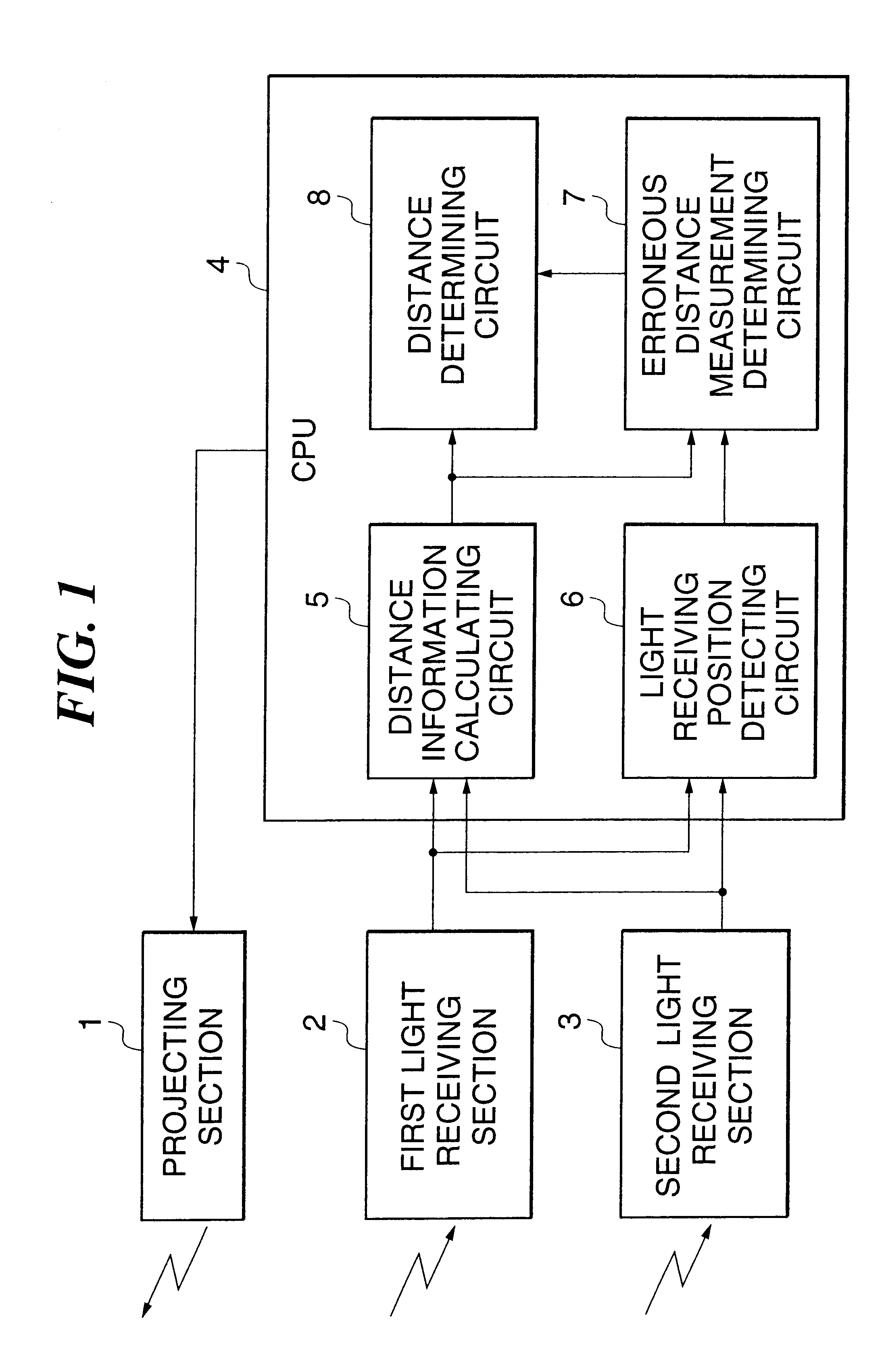
FIG. 1 is a block diagram showing the structure of a rangefinder device of a camera according to the present invention.

In FIG. 1, reference numeral 1 denotes a projecting section which emits a signal beam in the direction of a photographic subject, not shown in the figure, the operation of which is controlled by a CPU that will be described hereinafter.

Reference numeral 2 denotes a first light receiving section, and 3 denotes a second light receiving section, which output information (image signals) relating to light from the signal beam from the projecting section 1 which has illuminated the photographic subject and has been reflected to a distance information calculating section 5 and a light receiving position detecting circuit 6 within the CPU which will be described hereinafter. Reference numeral 4 denotes the CPU, in which are provided the distance information calculating circuit 5, the light receiving position detecting circuit 6, an erroneous distance measurement determining...

second embodiment

The operation of distance measurement in this second embodiment will be explained using the FIG. 7 flow chart.

In a step #601, the projecting section 1 is driven by the CPU 4 in FIG. 1.

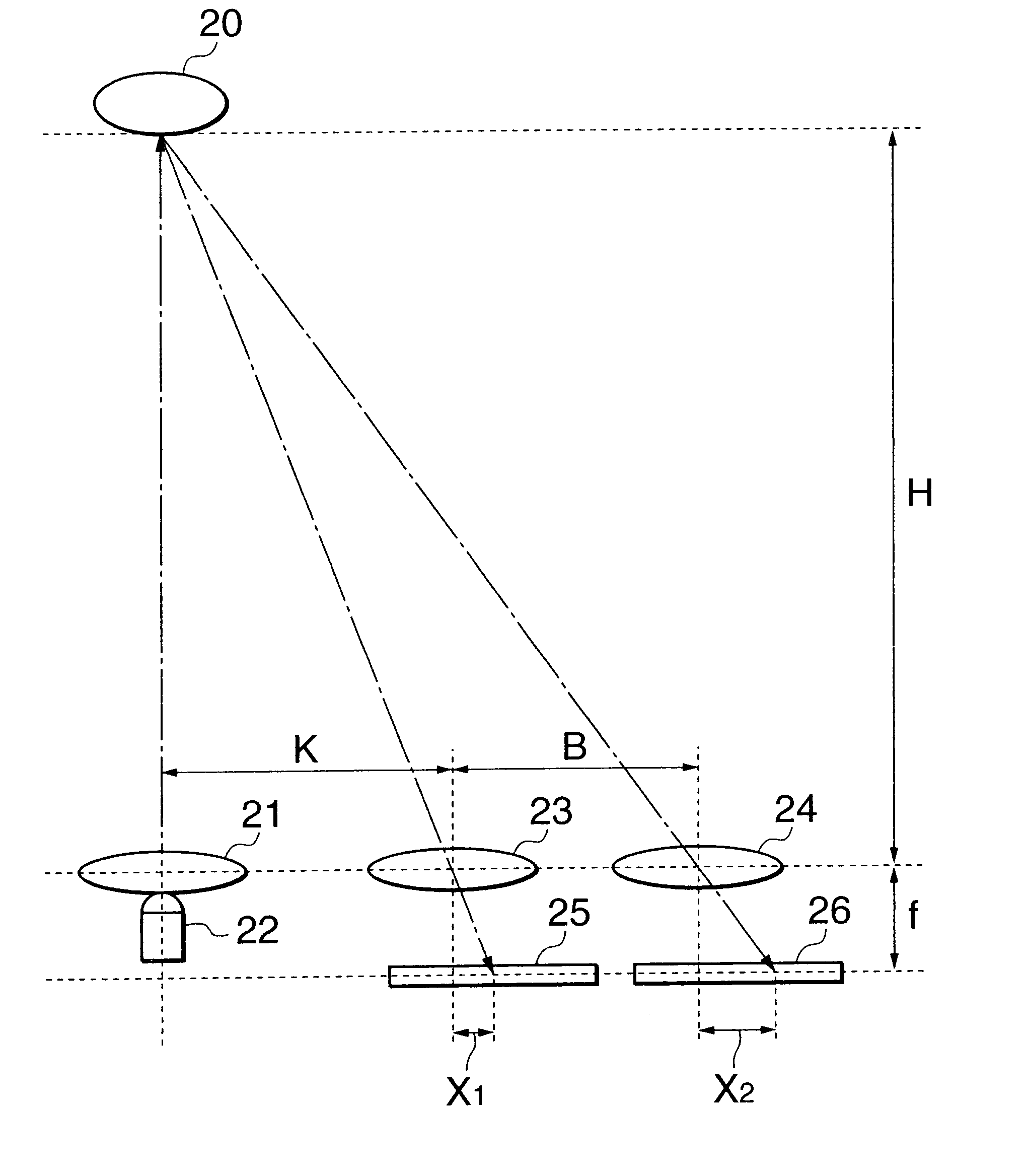
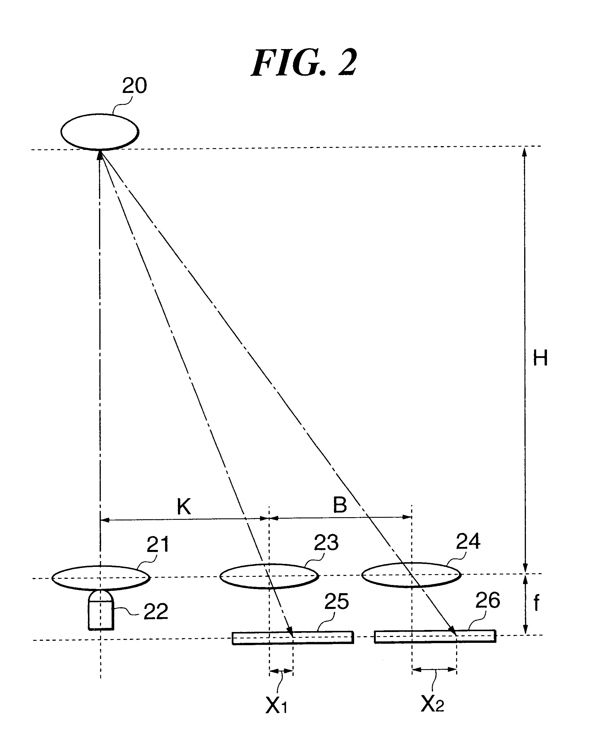
Next, in a step #602, the information relating to the distance to the photographic subject is calculated from the phase difference between the received light images which have been obtained by the first light receiving section 2 and the second light receiving section 3. (The distance is obtained using the above Equation (1)).

Next, in a step #603, the actual light receiving positions are detected by the light receiving position detecting circuit 6 from the light receiving positions which have been obtained by the first light receiving section 2 and the second light receiving section 3.

In a step #604, the erroneous distance measurement determining circuit 7 calculates the light receiving positions upon the first light receiving section 2 and the second light receiving section 3 from the distance informat...


PUM


Abstract

There are provided a rangefinder device which is capable of detecting that improper distance measurement through glass or the like has been performed, even when the glass is positioned at a certain or considerable distance from the camera, and a camera incorporating the rangefinder device. A projecting section projects a signal beam towards a photographic subject, and a light receiving section receives light from the photographic subject due to the projection via two different light paths. A distance information calculating circuit calculates distance information related to a distance to the photographic subject from the positional relationship between images received by the light receiving section. A position calculating circuit calculates first position information related to positions of the images received by the light receiving section based upon the calculated distance information. A determination circuit determines whether the calculated distance information is proper or improper, from the relationship between the first position information calculated by the position calculating circuit and second position information related to light receiving positions of the images that is obtained based upon an output from the light receiving section.< / PTEXT>

Description

1. Field of the InventionThe present invention relates to a rangefinder device for use in an auto-focus camera or the like, and more particularly to improvements in or to a rangefinder device having a function of detecting that improper distance measurement through glass or the like has been performed, and a camera that incorporates such a rangefinder device.2. Description of the Related ArtIn a conventional active type rangefinder device, a signal beam is projected towards an object whose range is to be determined (the "target object") by a projecting section, the reflected light therefrom is received by a light receiving section which is arranged at a specified distance corresponding to a base length from the projecting section, and the distance to the target object is calculated from the light receiving position (the reflected spot position).However, if glass is present between the photographic subject and the camera, a reflected signal beam is generated by the surface of the gla...

Claims


Application Information

Patent Timeline
Patent Type & Authority Patents(United States)
IPC IPC(8): G03B13/36G01B11/00G01C3/06G02B7/28G02B7/32
CPCG03B13/36
Inventor ICHIMIYA, TAKASHI
Owner CANON KK
Features
  • R&D
  • Intellectual Property
  • Life Sciences
  • Materials
  • Tech Scout
  • Unparalleled Data Quality
  • Higher Quality Content
  • 60% Fewer Hallucinations
Learn More