Modular low profile cooling system

a cooling system and module technology, applied in the field of cooling systems, can solve the problems of equipment failure, total system failure, reduced system performance, etc., and achieve the effect of greater and greater efficiency

Inactive Publication Date: 2003-11-11
VERTIV CORP +1
View PDF11 Cites 52 Cited by
  • Summary
  • Abstract
  • Description
  • Claims
  • Application Information

AI Technical Summary

Benefits of technology

The growth of the computer industry and telephony over the past few decades has been phenomenal. The integration of these technologies, for example, in telecommunications switching and in datacenters, has lead to greater and greater efficiencies as larger numbers of communications are handled by fewer components, which are typically housed in a central control room.
The present invention overcomes the above-discussed shortcomings and satisfies a significant need for reducing space requirements while increasing the cooling capacity of cooling systems.

Problems solved by technology

As is readily apparent, if equipment is not effectively cooled, the internal temperature of the electronic components in the equipment substantially increases, thereby leading to significantly reduced system performance and, in some cases, total system failure.
If a cooling system inefficiently cools the equipment, either the equipment may fail due to increased operating temperature or the costs for cooling the equipment may be unnecessarily high.

Method used


Image

  • Modular low profile cooling system
  • Modular low profile cooling system

Examples


Embodiment Construction

The present invention will now be described more fully hereinafter with reference to the accompanying drawing in which a preferred embodiment of the invention is shown. This invention may, however, be embodied in many different forms and should not be construed as being limited to the embodiment set forth herein.

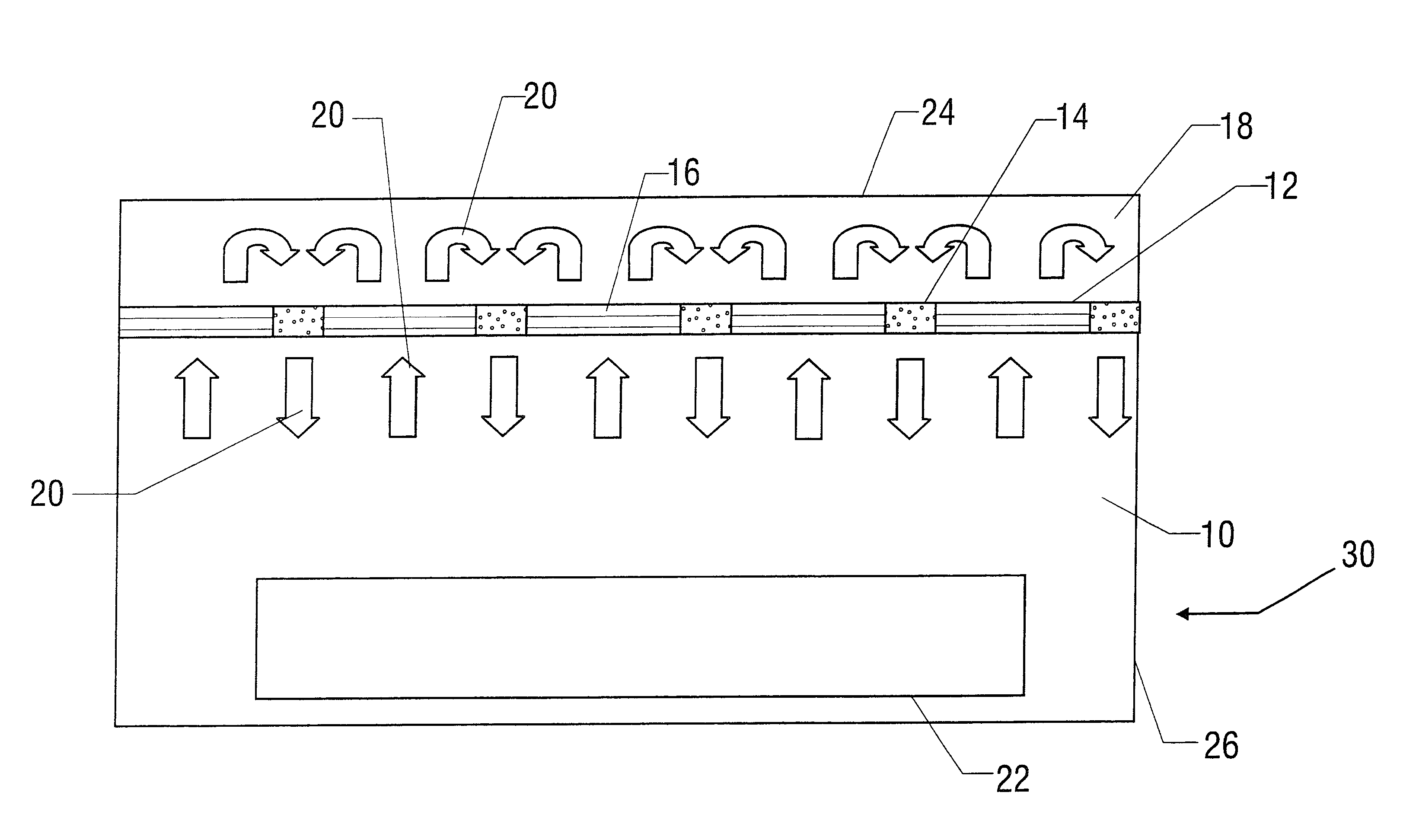
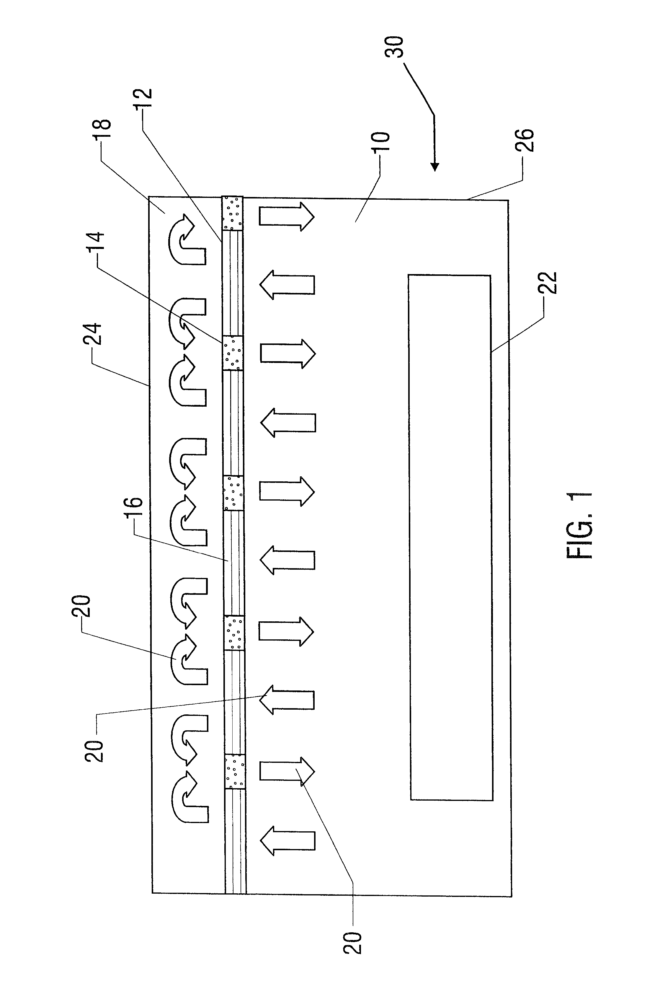
Referring to FIG. 1, there is shown a cooling system 10 according to an embodiment of the present invention. Cooling system 10 is adapted to include a cooling coil 12 and a fan 14. The fan 14 and the cooling coil 12 are abutted so as to form a second surface 16. A first surface 24 and the second surface 16 are each joined to the wall 26 so as to create an enclosed area which is to be used as a plenum 18. As the fan 14 forces air 20 out of the plenum 18, an area of reduced pressure is created in the plenum 18 which in turn draws the air 20 through the cooling coils 12 where heat is transferred from the air 20 and into the cooling coils 12. The air is then further drawn into t...


PUM


Abstract

A method and system for high density modular cooling system is disclosed. Cooling coils and fans are interleaved so as to cover all usable space with the enclosed area behind the interleaved cooling coils and fans acting as a plenum. A cooling fluid is circulated through the cooling coils by the interleaved fans.

Description

1. Technical Field of the InventionThe present invention relates to cooling systems for cooling electronic equipment, and particularly to high density systems such as ceiling and floor mounted systems, to allow increased cooling capacity in a smaller volume.2. Background and Objects of the InventionThe growth of the computer industry and telephony over the past few decades has been phenomenal. The integration of these technologies, for example, in telecommunications switching and in datacenters, has lead to greater and greater efficiencies as larger numbers of communications are handled by fewer components, which are typically housed in a central control room.As is readily apparent, if equipment is not effectively cooled, the internal temperature of the electronic components in the equipment substantially increases, thereby leading to significantly reduced system performance and, in some cases, total system failure. If a cooling system inefficiently cools the equipment, either the e...

Claims


Application Information

Patent Timeline
Patent Type & Authority Patents(United States)
IPC IPC(8): H05K7/20
CPCH05K7/20745H05K7/2059
Inventor STAHL, LENNART
Owner VERTIV CORP
Why Eureka
Try Eureka