Bicycle pedal

a pedal and bicycle technology, applied in the field of bicycle pedals, can solve the problems of undesirable clipless pedals, complicated and expensive manufacturing, and undesirable clipless pedals

Inactive Publication Date: 2003-11-18
SHIMANO INC
View PDF19 Cites 57 Cited by
  • Summary
  • Abstract
  • Description
  • Claims
  • Application Information

AI Technical Summary

Benefits of technology

Another object of the present invention is to provide a platform bicycle pedal which is relatively simple and inexpensive to manufacture and assemble.
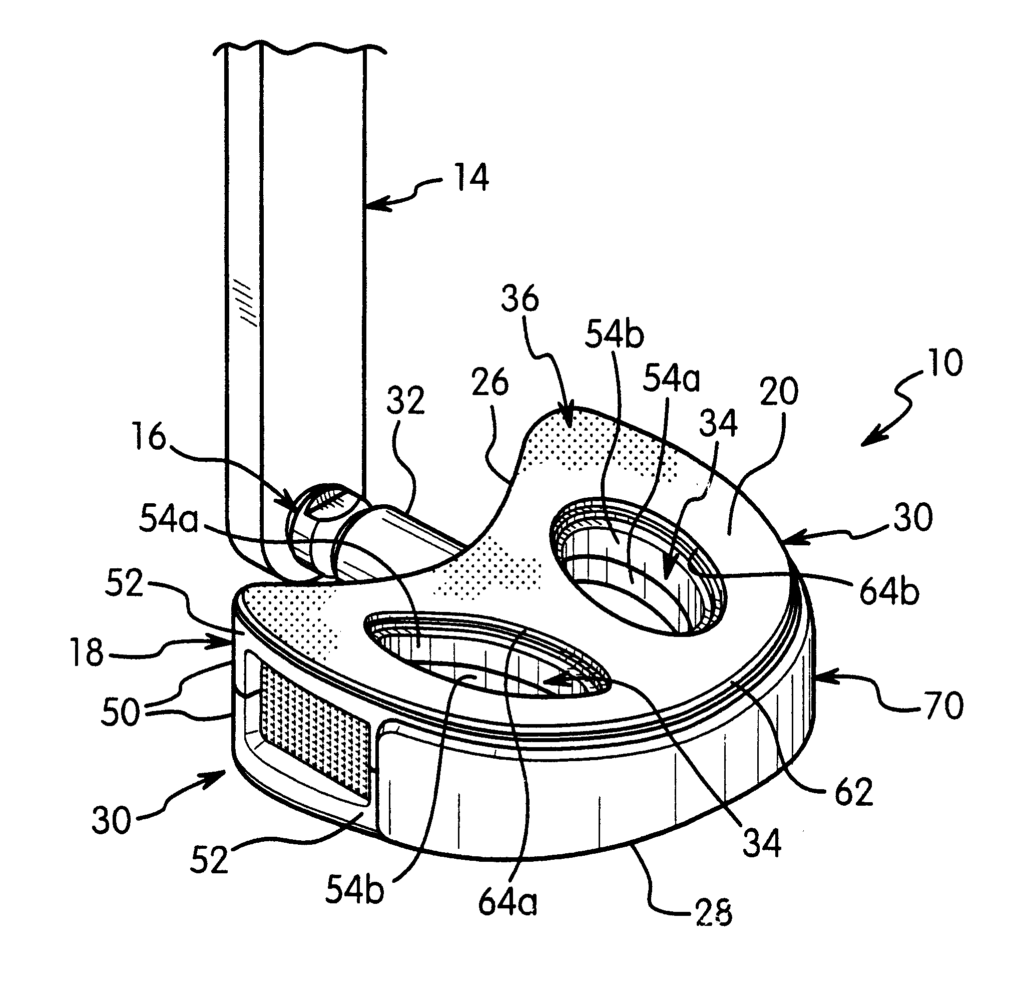
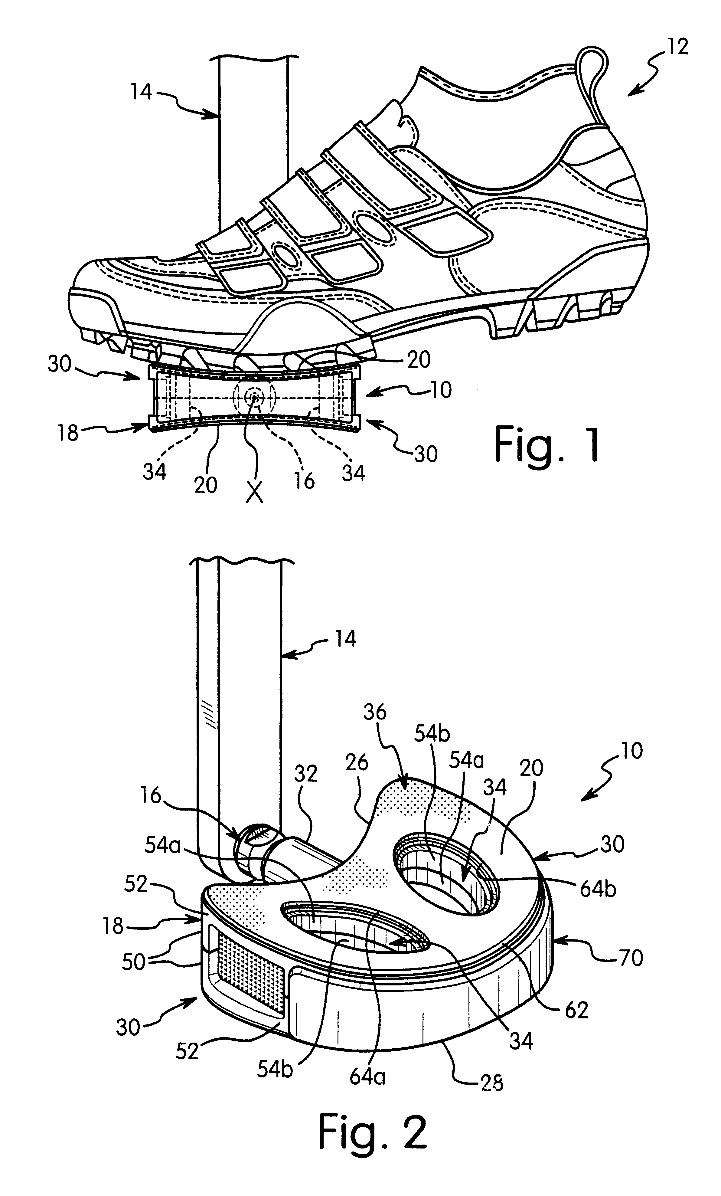
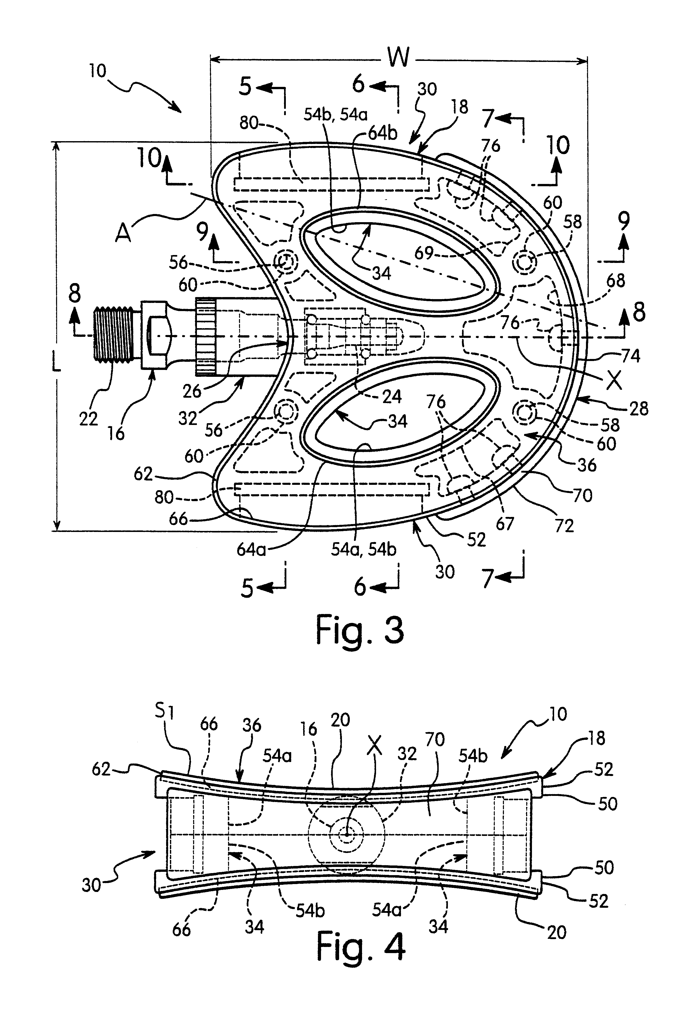
The foregoing objects can basically be attained by providing a bicycle pedal comprising a pedal shaft, a pedal body and an abrasive sheet. The pedal shaft has a first end adapted to be coupled to a bicycle crank and a second end. The pedal body is rotatably coupled to the second end of the pedal shaft. The pedal body has a shoe engagement surface with a recess. The abrasive sheet is fixedly coupled within the recess to enhance engagement of the pedal with a shoe.

Problems solved by technology

However, these clipless bicycle pedals can be complicated and expensive to manufacture.
Additionally, these clipless pedals can be undesirable in certain riding conditions.
For example, clipless bicycle pedals can be undesirable when the cyclist needs to continually engage and release the cyclist's shoe from the clipless pedal.
Another problem with most clipless pedals is that they are quite small and can have several moving parts.
As a result of these types of pedal designs, the moving parts often can become clogged with dirt or mud in wet riding conditions.
Furthermore, these clipless pedals can be complicated and expensive to manufacture and assemble.
While these platform pedals allow the cyclist to repeatedly remove the cyclist's shoe from the pedal during cornering and replace the cyclist's shoe on the pedal after cornering, these pedals often lack the efficient power transfer characteristics of a clipless bicycle pedal.
Additionally, platform pedals are usually heavy and lack the secure feel of clipless pedals.
Moreover, these platform pedals can also become clogged with dirt or mud in wet riding conditions.
Furthermore, some of these platform pedals can be complicated and expensive to manufacture and assemble.

Method used


Image

  • Bicycle pedal
  • Bicycle pedal
  • Bicycle pedal

Examples


third embodiment

Referring now to FIGS. 13-15, a bicycle pedal 210 in accordance with a third embodiment of the present invention is illustrated. The basic construction of the third embodiment is similar to the basic construction of the first embodiment, discussed above. However, the shape of pedal 210 has been modified to illustrate some alternatives to the basic concept of the present invention, as explained below. In view of the similarities between pedal 210 of the third embodiment and pedal 10 of the first embodiment, the parts of pedal 210 that are similar to the parts of pedal 10 will not be discussed and / or illustrated in detail herein. Rather, only the significant differences between pedal 210 and pedal 10 will be discussed and / or illustrated herein. Accordingly, it will be apparent to those skilled in the art from this disclosure that the description of the first embodiment applies to this third embodiment, except for as explained below.

Bicycle pedal 210 basically includes a pedal shaft 21...

fourth embodiment

Referring now to FIGS. 16-18, a bicycle pedal 310 in accordance with a fourth embodiment of the present invention is illustrated. The basic construction of the bicycle pedal 310 of the fourth embodiment is similar to the basic construction of the bicycle pedal 10 of the first embodiment, discussed above. However, the shape of pedal 310 has been modified to illustrate a further alternative of the basic concept of the present invention, as explained below. In view of the similarities between the pedal body 310 of the fourth embodiment and the pedal body 10 of the first embodiment, the parts of the pedal 310 that are similar to the parts of the pedal 10 will not be discussed and / or illustrated in detail herein. Rather, only the significant differences between pedals 310 and pedal 10 will be discussed and / or illustrated herein. Accordingly, it will be apparent to those skilled in the art from this disclosure that the description of the first embodiment applies to this fourth embodiment,...

fifth embodiment

Referring now to FIGS. 19-21, a bicycle pedal 410 in accordance with a fifth embodiment of the present invention is illustrated. The basic construction of the fifth embodiment is similar to the basic construction of the first embodiment, discussed above. However, the shape of pedal 410 has been modified to illustrate an alternative embodiment of the present invention, as explained below. In view of the similarities between pedal 410 of the fifth embodiment and pedal 10 of the first embodiment, the parts of pedal 410 that are similar to the parts of pedal 10 will not be discussed and / or illustrated in detail herein. Rather, only the significant differences between pedal 410 and pedal 10 will be discussed and / or illustrated herein. Accordingly, it will be apparent to those skilled in the art from this disclosure that the description of the first embodiment applies to this fifth embodiment, except for as explained below.

Bicycle pedal 410 basically includes a pedal shaft 416 adapted to ...


PUM


Abstract

The bicycle pedal includes a pedal shaft, a pedal body and an abrasive sheet coupled to a shoe engagement surface to enhance engagement of the pedal with a shoe. The pedal body is rotatably coupled to the second end of the pedal shaft. The shoe engagement surface preferably includes a recess with first and second curvatures. The first curvature has a first radius and the second curvature has a second radius larger than the first radius. The abrasive sheet is preferably coupled within the recess. Frictional characteristics are improved by a method including the steps of forming a pedal body with a recess and coupling an abrasive sheet in the recess of the pedal body. The abrasive sheet is positioned to resist peeling of the abrasive sheet from the pedal body. The pedal body can be formed of one or more pieces.

Description

1. Field of the InventionThis invention generally relates to a bicycle pedal. More specifically, the present invention relates to a platform type bicycle pedal, which has improved frictional characteristics.2. Background InformationBicycling is becoming an increasingly popular form of recreation as well as a means of transportation. Moreover, bicycling has become a very popular competitive sport. Whether the bicycle is used for recreation, transportation or competition, the bicycle industry is constantly improving their components. One particular component of the bicycle, which has been extensively redesigned over the past years, is the bicycle pedal.In recent years, bicycle pedals have been designed for specific purposes, such as for pleasure, off-road biking, road racing, etc. Generally, there are two basic types of bicycle pedals available. One particular type of bicycle pedal, which is gaining more popularity, is the step-in or clipless pedal, which releasably engages a cleat se...

Claims


Application Information

Patent Timeline
Patent Type & Authority Patents(United States)
IPC IPC(8): B62M3/00B62M3/08
CPCB62M3/08Y10T74/20912Y10T74/2168
Inventor OKAJIMA, SHINPEIKOJIMA, MASAO
Owner SHIMANO INC
Why Eureka
Try Eureka