Termination unit for a coaxial flue pipe

a technology of coaxial flue pipe and terminal unit, which is applied in the direction of combustion process, combustion treatment, domestic heating details, etc., can solve the problems of needing to have the burner serviced and disassembly and other problems

Inactive Publication Date: 2003-11-18
MICLAU S R I
View PDF28 Cites 26 Cited by
  • Summary
  • Abstract
  • Description
  • Claims
  • Application Information

AI Technical Summary

Benefits of technology

It is a feature of the present invention to provide a termination unit which substantially overcomes the disadvantages of the prior art and which is capable of dampening wind striking the termination unit at velocities of up to about 60 to 70 m.p.h.

Problems solved by technology

If a pilot flame is extinguished, as is the case with some prior art designs, gas can infiltrate an area where the gas combustion device is used and could result in disastrous circumstances should the equipment not be provided with flame sensor and automatic gas shut-off valves.
When the pilot is extinguished, there is often the need to have the burner serviced, and this is costly.

Method used


Image

  • Termination unit for a coaxial flue pipe
  • Termination unit for a coaxial flue pipe
  • Termination unit for a coaxial flue pipe

Examples


Embodiment Construction

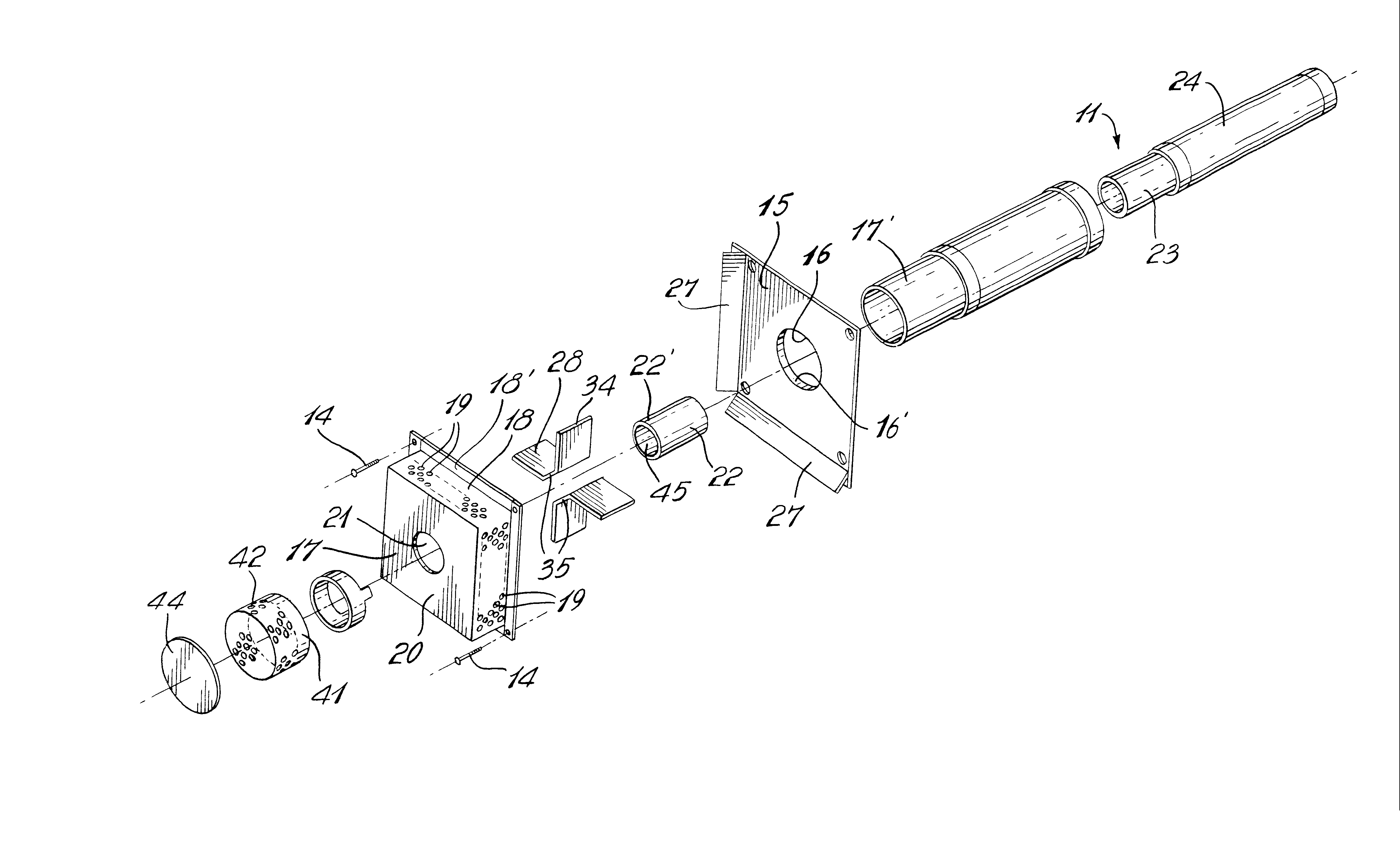
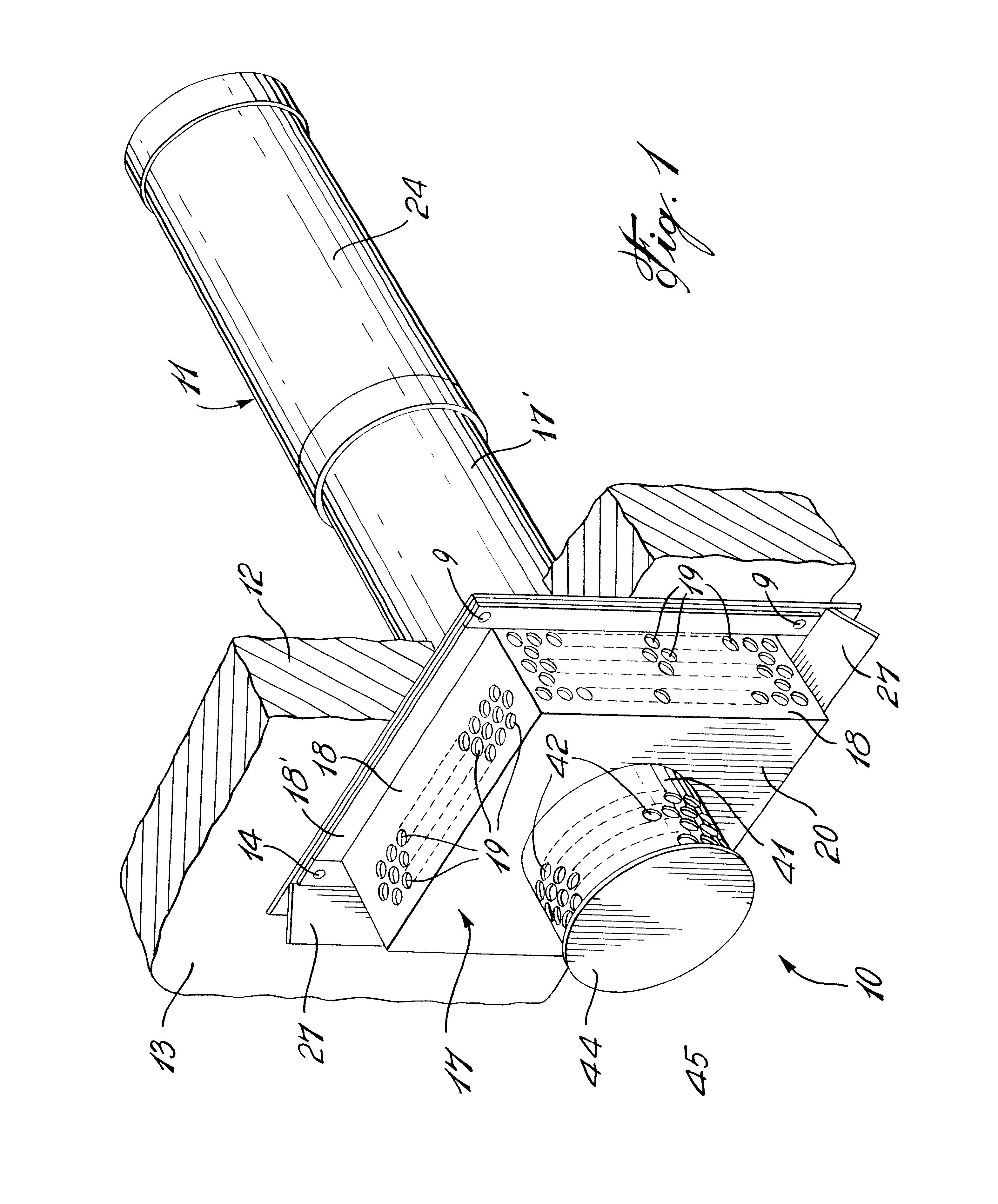
Referring now to the drawings and more particularly to FIG. 1, there is shown generally at 10 the termination unit of the present invention secured to a horizontal vent pipe 11 of a gas combustion device such as a fireplace, furnace, hot water heater, etc. which are provided with a combustion chamber and a burner, as is well known in the art. As hereinshown, the vent pipe 11 is a coaxial pipe and it extends through an outer wall 12 of a building structure. The termination unit 10 is secured to the outer face 13 of the outer wall 12 by fasteners 14 or other securement means.

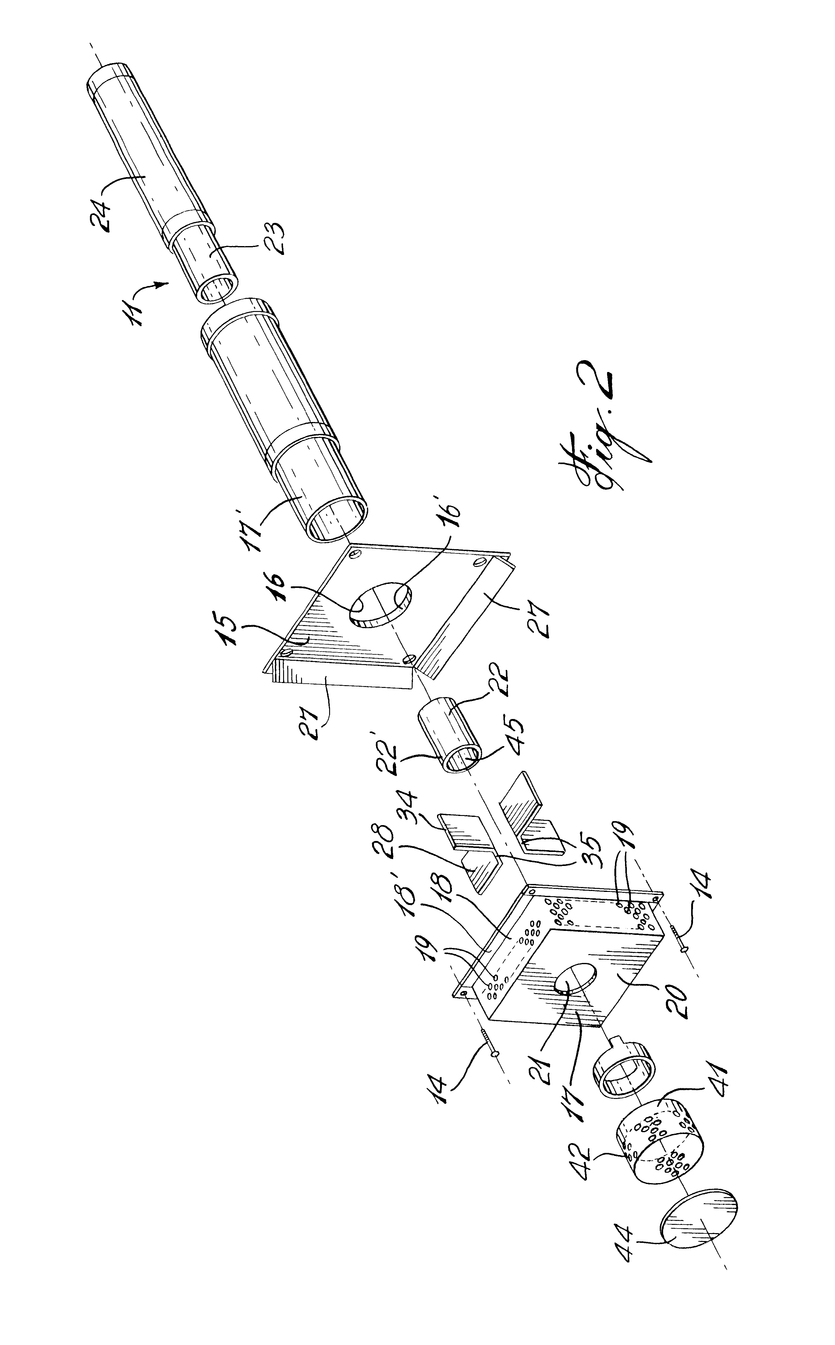
With reference now to FIG. 2, a detailed description of the termination unit will now be described. The termination unit is comprised of a wall mounting means in the form of a square rectangular mounting plate 15. The mounting plate is provided with a circular hole 16 centrally thereof and having a circumferential flange 16' which is dimensioned to be secured about the outer sleeve 17' of the coaxial vent pipe 11 ...


PUM


Abstract

A termination unit for a through-the-wall horizontal vent of a gas combustion device having a combustion chamber and a burner, is described. The termination unit comprises a wall mounting plate which is secured to a vertical wall outer surface and about an outer sleeve of a coaxial flue pipe. A fresh air chamber is secured to the wall mounting plate. An exhaust end of an exhaust flue pipe extends through the wall mounting plate and the fresh air chamber to exit through an outer wall of the chamber. Air intake ports are provided in an outer peripheral wall of the chamber to supply fresh air to a coaxial passage between the exhaust flue pipe and the outer sleeve to feed the combustion chamber. An air baffle is provided in the chamber about the exhaust end of the flue pipe and extends through the chamber. Wind deflector flanges are disposed in spaced relationship about the air intake ports of the chamber.

Description

The present invention relates to a termination unit for a through the wall horizontal vent of a coaxial flue pipe and wherein the termination unit is capable of dampening wind up to about 65 m.p.h. to prevent the pilot flame in the combustion chamber from extinguishing due to air disturbance propagating to the pilot flame.Various types of termination unit designs are known and examples thereof are illustrated in U.S. Pat. Nos. 2,998,764, 4,940,042 and 3,435,816, which are believed to represent the closest prior art. All of these termination units are efficient in dampening wind striking against the unit in the area of the air intake but are efficient to a maximum wind speed of up to 45 m.p.h. On occasion, the pilot flame in a combustion furnace, hot water heater, etc., has been known to extinguish by a gust of air entering the termination unit, air feed conduit and propagating in a down draft to the pilot flame through the coaxial air feed passage. It is therefore desirable to provi...

Claims


Application Information

Patent Timeline
Patent Type & Authority Patents(United States)
IPC IPC(8): F23J11/06F23L17/04F23L17/12F23J11/00F23L17/00
CPCF23J11/06F23L17/12F23L17/04F23J2900/13005
Inventor LESAGE, CLAUDE
Owner MICLAU S R I
Why Eureka
Try Eureka