Igniting operation mechanism of piezoelectric ignition lighter

a piezoelectric ignition and operation mechanism technology, applied in the direction of burners, combustion processes, lighting and heating apparatuses, etc., can solve the problems of heavy load, poor operability, inconvenience for all users,

Inactive Publication Date: 2003-11-18
TOKAI
View PDF9 Cites 7 Cited by
  • Summary
  • Abstract
  • Description
  • Claims
  • Application Information

AI Technical Summary

Benefits of technology

The ignition actuation mechanism for piezoelectric ignition lighter according to the present invention is a type having a piezoelectric mechanism for generating discharge voltage that causes spark between discharge electrodes to ignite fuel gas by actuation of the actuation member in a single direction. It features in the load (actuation load) resisting operation of the actuation member being sharply increased in the way of actuation stroke for generating discharge voltage by depressing the piezoelectric mechanism. In this manner, the load is light at the initial stage of the ignition operation but becomes heavy at the final stage, thereby avoiding misuse by any person having poor knowledge of proper use but maintaining excellent operability for normal users.

Problems solved by technology

Unfortunately, they are not preferable in terms of safety because they can carelessly ignite by children or other persons who lack in knowledge about their proper use.
However, such conventional ignition actuation mechanisms of piezoelectric ignition lighters for improving safety by increasing actuation load are inconvenient to all users.
Because the actuation load is heavy over the entire actuation stroke of ignition operation of the piezoelectric mechanism and provides very heavy load from the initial stage of the ignition operation.
Operability is poor if the timing to increase the actuation load is too early.
However, too heavy actuation load leads to poor operability.

Method used


Image

  • Igniting operation mechanism of piezoelectric ignition lighter
  • Igniting operation mechanism of piezoelectric ignition lighter
  • Igniting operation mechanism of piezoelectric ignition lighter

Examples


Embodiment Construction

Now, an embodiment of the present invention will be described in detail by reference to accompanying drawings.

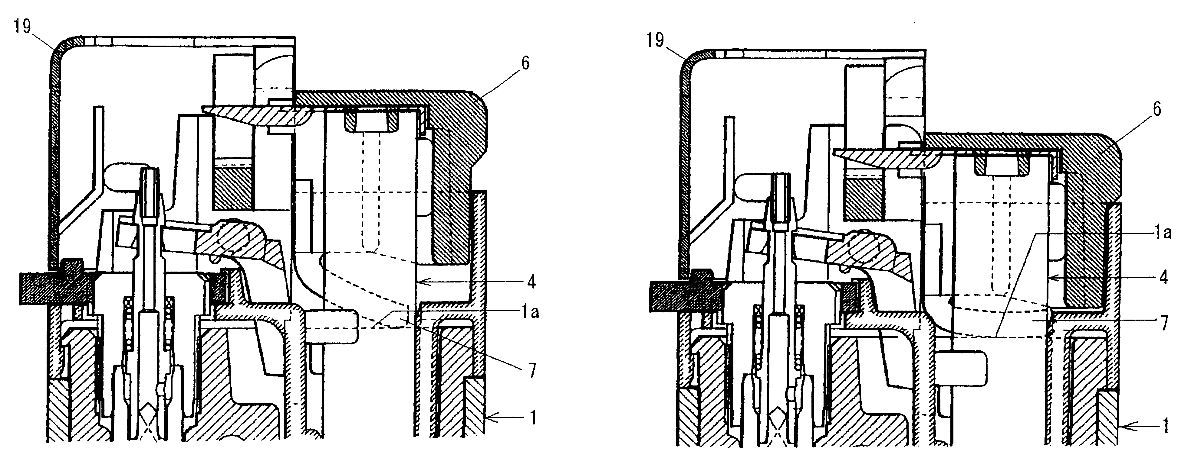
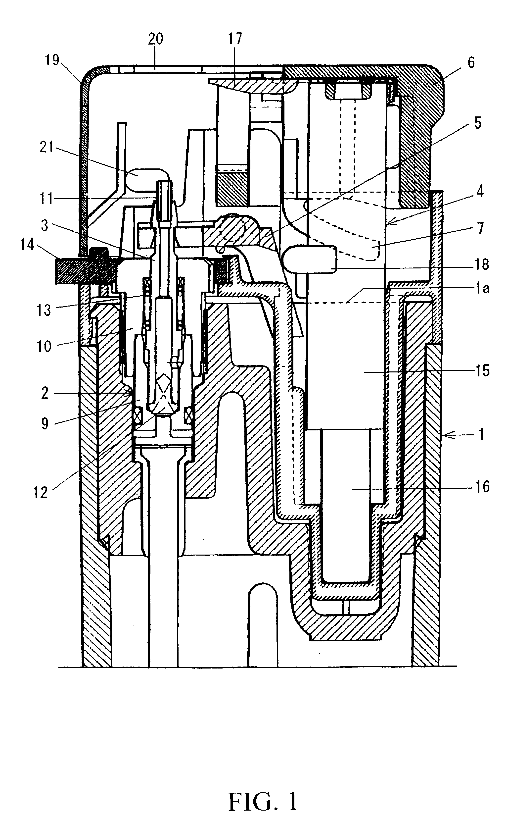
As illustrated in FIG. 1, the piezoelectric ignition lighter comprises a valve mechanism 2 to open and close a gas path at the top of a lighter body 1 containing fuel gas for controlling the amount of fuel gas, a nozzle 3 for emitting the fuel gas from the valve mechanism 2, a piezoelectric mechanism 4 for generating discharge voltage, a gas lever 5 for opening the valve mechanism 3 in ganged with the piezoelectric mechanism 4 to emit fuel gas from the nozzle 3 and an actuation cap 6 for actuating the piezoelectric mechanism 4 and actuating the gas lever 5 by way of a lever pusher 18 that is described hereinafter and acts as one electrode of the piezoelectric mechanism 4.

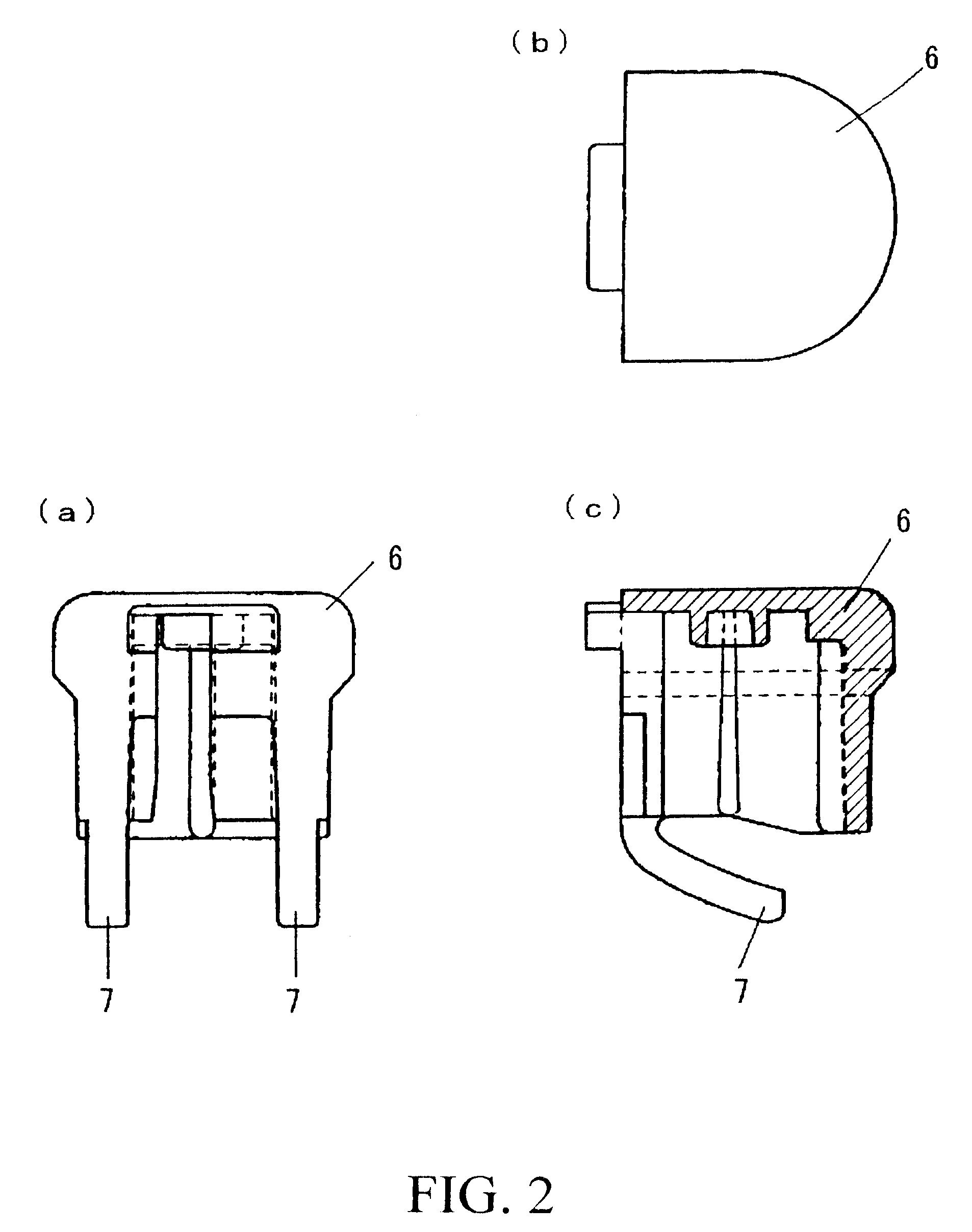
The actuation cap 6 is made by molding polyacetal resin and is an integral member of a cap body including a generally semi-oval actuation portion and a sliding portion extending below the actuation portion a...


PUM


Abstract

The present invention intends to provides a piezoelectric ignition lighter capable of avoiding misuse by children but maintaining excellent operability for normal users without unreasonably increasing actuation load at the initial ignition operation. For this end, the piezoelectric ignition lighter has a valve mechanism, a nozzle 3 and a piezoelectric mechanism 4 at the top of a lighter body 1 and ignites by actuation of an actuation cap 6 integrally molded of polyacetal resin with torsion plates 7,7. The torsion plates 7,7 are separated from the upper end surface 1a of the lighter body 1 by a gap equal to about 60%~90% of the actuation stroke in the non-actuated condition to provide a normal (light) actuation load at the initial actuation stage. After engagement of the torsion plates 7,7 with the upper end surface of the lighter body 1, resilient load of the torsion plates is added to normal load, thereby increasing the actuation load.

Description

The present invention relates generally to a piezoelectric ignition lighter, more specifically to an ignition mechanism for a piezoelectric ignition lighter with enhanced safety by increasing actuation load (a load to resist actuation).BACKGROUND OF INVENTIONPiezoelectric ignition lighters are very convenient because they can ignite by simple actuation or pushing-down of their actuation members. Unfortunately, they are not preferable in terms of safety because they can carelessly ignite by children or other persons who lack in knowledge about their proper use.One solution to avoid careless or inadvertent ignition of such lighters by persons who have no knowledge of proper use is to increase actuation load as disclosed, for example, in U.S. Pat. No. 5,971,751. That is, a coil spring and a resilient member are disposed inside the actuation button to provide resilient loads of the coil spring and the resilient member to the normal actuation load of the piezoelectric mechanism. In this ...

Claims


Application Information

Patent Timeline
Patent Type & Authority Patents(United States)
IPC IPC(8): F23Q2/00F23Q2/28
CPCF23Q2/287
Inventor ICHIKAWA, TOSHIHIROADACHI, NAOTO
Owner TOKAI
Why Eureka
Try Eureka