Method for producing electrode for lithium secondary battery
a lithium secondary battery and electrode technology, applied in the direction of cell components, cell component details, electrochemical generators, etc., can solve the problems of reducing the current-collecting characteristics, short-circuiting internal, and inability to achieve high productivity
- Summary
- Abstract
- Description
- Claims
- Application Information
AI Technical Summary
Benefits of technology
Problems solved by technology
Method used
Image

Examples
experiment 2
(Experiment 2)
[Production of Negative Electrode]
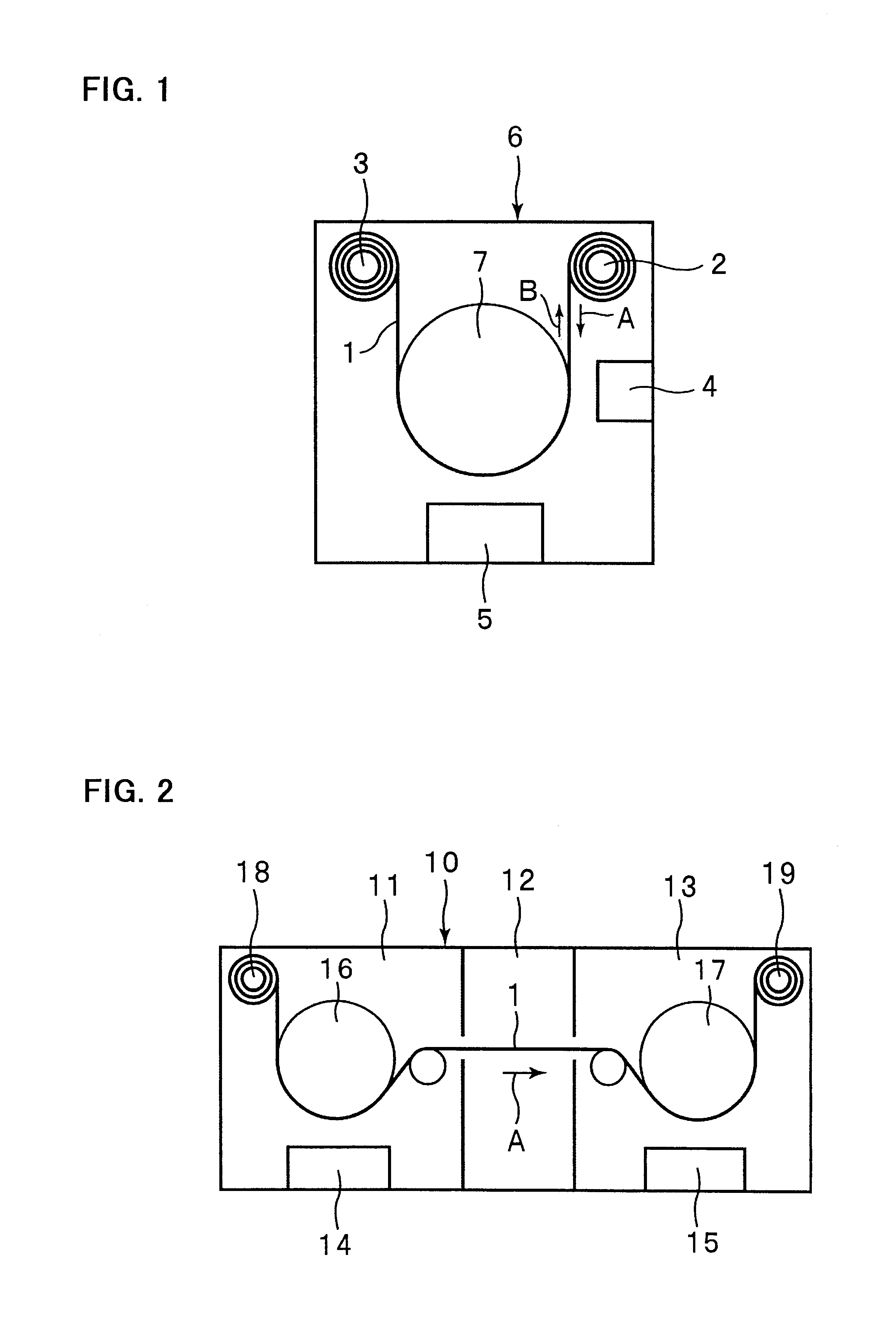
An interface layer and an active material layer were formed on a current collector in the same manner described in Experiment 1, except that a thin-film forming apparatus shown in FIG. 2 was used.
The thin-film forming apparatus 10 shown in FIG. 2 is partitioned into three chambers: a sputtering chamber 11, a preparatory chamber 12 and a vapor evaporation chamber 13. Not only the sputtering chamber 11 and the vapor evaporation chamber 13, but also the preparatory chamber 12 are evacuated, so that the amount of flow of Ar gas for sputtering into the vapor evaporation chamber 13 can be reduced. A sputtering source 14 is placed in the sputtering chamber 11, and a vapor evaporation source 15 is placed in the vapor evaporation chamber 13. The sputtering source 14 and the vapor evaporation source 15 are the same as the sputtering source 4 and the vapor evaporation source 5 in the apparatus shown in FIG. 1.
The current collector 1, wound up aro...
experiment 3
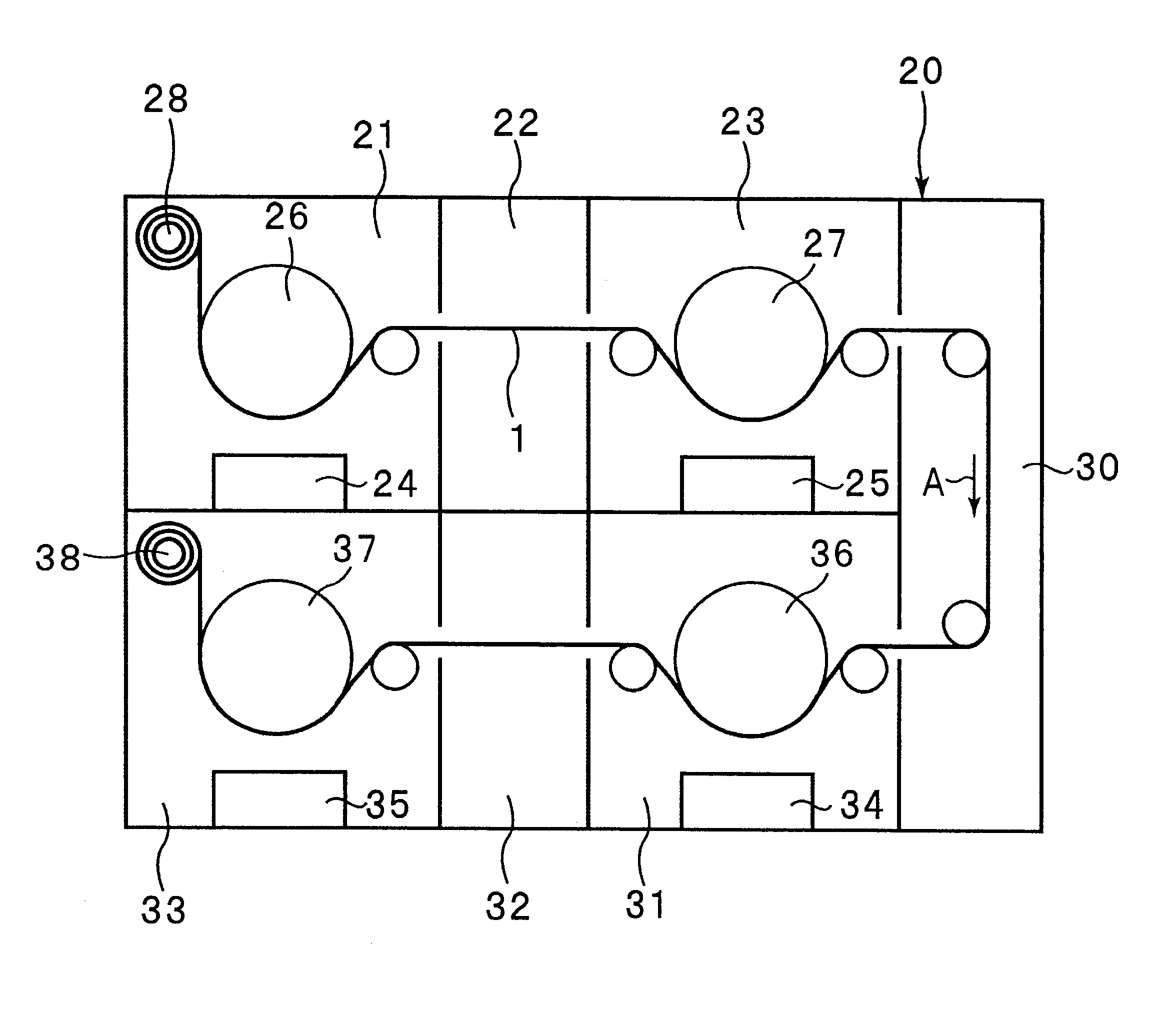
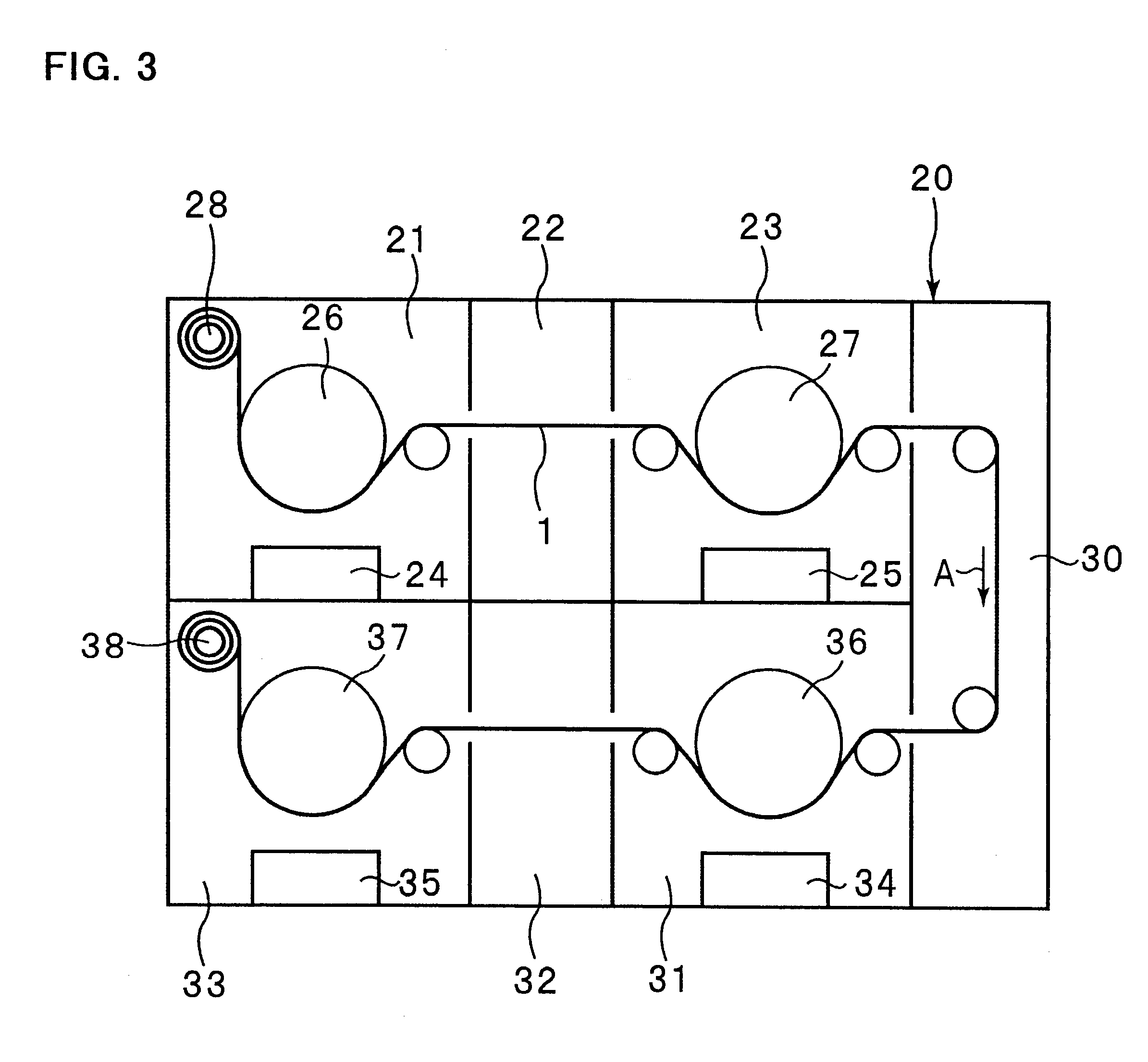
(Experiment 3)
A silicon thin film was formed on a current collector in the same manner described in Experiment 1, except that a thin-film forming apparatus shown in FIG. 3 was used.
As shown in FIG. 3, the thin-film forming apparatus 20 includes a first sputtering chamber 21, a first preparatory chamber 22 and a first vapor evaporation chamber 23 each for formation of an interface layer and an active material layer on one surface of the current collector 1. The apparatus 20 also includes a second sputtering chamber 31, a second preparatory chamber 32 and a second vapor evaporation chamber 33 each for formation of an interface layer and an active material layer on the other surface of the current collector 1. A third preparatory chamber 30 is provided between the first vapor evaporation chamber 23 and the second sputtering chamber 31. Support rollers 26, 27, 36 and 37 are provided in the first sputtering chamber 21, the first vapor evaporation chamber 23, the second sputtering chamber...
PUM
| Property | Measurement | Unit |
|---|---|---|
| thickness | aaaaa | aaaaa |
| thickness | aaaaa | aaaaa |
| thickness | aaaaa | aaaaa |
Abstract
Description
Claims
Application Information
 - R&D
- Intellectual Property
- Life Sciences
- Materials
- Tech Scout
- Unparalleled Data Quality
- Higher Quality Content
- 60% Fewer Hallucinations
Browse by: Latest US Patents, China's latest patents, Technical Efficacy Thesaurus, Application Domain, Technology Topic, Popular Technical Reports.
© 2025 PatSnap. All rights reserved.Legal|Privacy policy|Modern Slavery Act Transparency Statement|Sitemap|About US| Contact US: help@patsnap.com