
Adapting receiver thresholds to improve rate-based flow control

a receiver threshold and rate-based flow control technology, applied in the field of computer programming, can solve problems such as delays and inefficiencies, data packet loss or the need to send again, and network resources such as network bandwidth are not being used efficiently

Inactive Publication Date: 2003-12-02
IBM CORP
View PDF10 Cites 132 Cited by
  • Summary
  • Abstract
  • Description
  • Claims
  • Application Information

AI Technical Summary

Problems solved by technology

If too much data is being sent from a sending component to a receiving component, the buffers in which data is stored at intermediate nodes along the path between them (or at the receiver itself) may overflow, causing loss of data packets or the need to resend them.
Or, if the buffers do not actually overflow, the network may become congested under heavy transmission loads, resulting in delays and inefficiencies.
On the other hand, if the sender has data to be sent, but is sending it at a very slow rate when excess capacity exists in the network, then network resources such as network bandwidth are not being used efficiently.
The larger the difference between the receiver's interval and the sender's interval, the greater the delay that is being experienced in the network.
If the DCS is above the threshold, then too much delay is being experienced.
There are a number of drawbacks to using a fixed threshold value.
For example, it may be that the existing conditions are different than expected, such that the static threshold does not properly control transmission rates.
This is quite error-prone, however, because a number of complex interrelated factors must be considered when choosing a proper threshold value.
In addition, it provides only a temporary solution as conditions may change again, making the new threshold no longer adequate.
Or, bandwidth may have been added after the threshold was originally set, so that the original setting was correct at the time but no longer is appropriate for the current capacity.

Method used


Image

  • Adapting receiver thresholds to improve rate-based flow control
  • Adapting receiver thresholds to improve rate-based flow control
  • Adapting receiver thresholds to improve rate-based flow control

Examples


Embodiment Construction

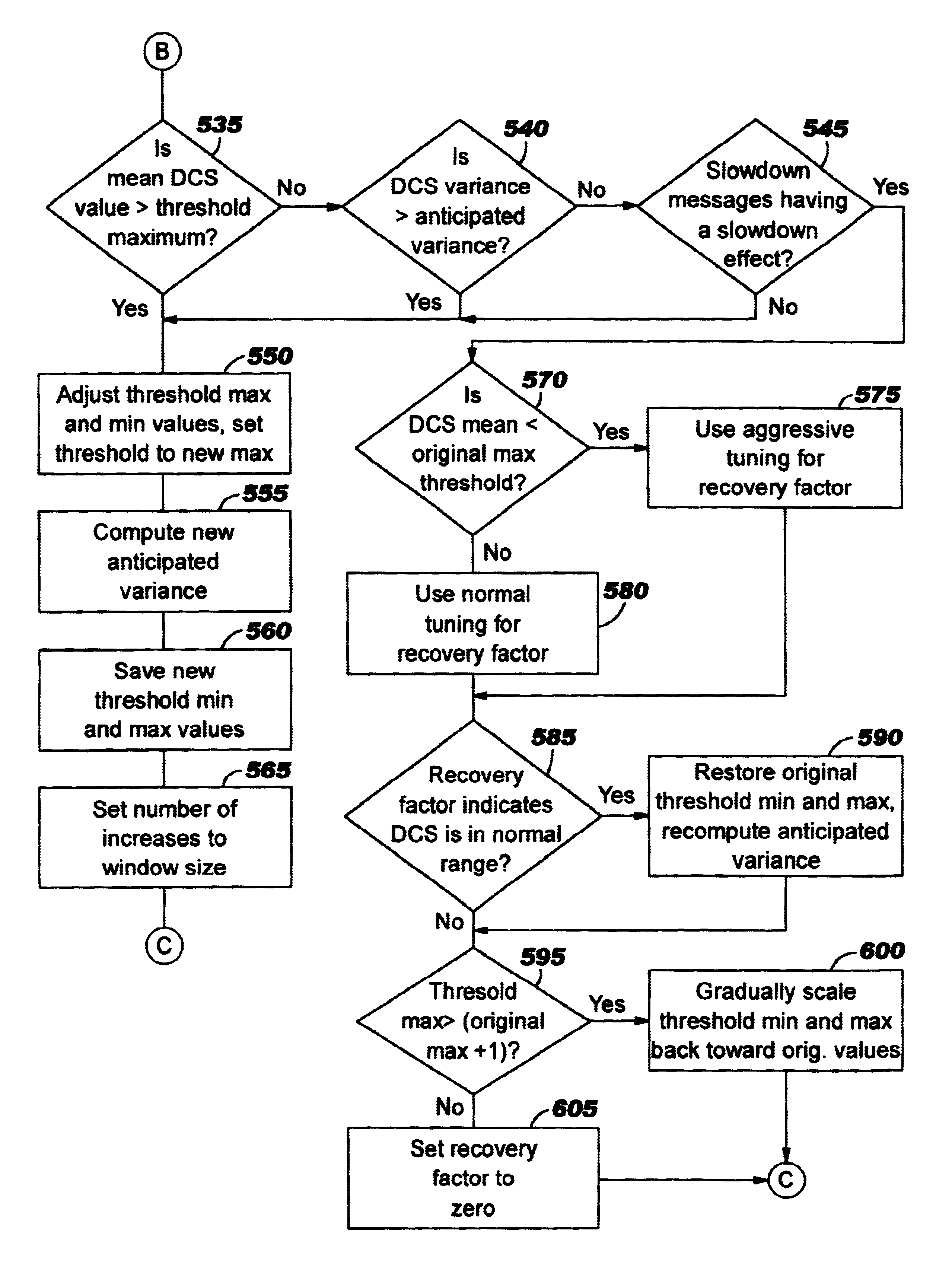
The process of the first preferred embodiment begins at Block 500 of FIG. 5A. FIG. 5A represents the logic used in computing a number of values that are used subsequently (by Blocks 535, 540, and 545 of FIG. 5B) to detect a foreign protocol. (As discussed above, a foreign protocol is one not using the techniques of the present invention.) At Block 500, a time averaging coefficient, "Avg_Coef" is computed. This value will be used to detect a foreign protocol, and is also used if a foreign protocol is detected, and is inapplicable otherwise. Avg_Coef is set to the smaller of a DCS averaging limit or the result of dividing the measurement interval by the DCS averaging interval, according to the following equation: ##EQU1##

The variable "Measurement_Interval" corresponds to the time since the most recent rate request message was received, computed as the receiver's delay (T4-T2). In the preferred embodiment, the averaging limit is a constant value of 0.2 seconds, and the averaging interv...


PUM


Abstract

A technique for adapting receiver thresholds to improve rate-based flow control in a data communications network. With this invention, the flow control process becomes self-calibrating such that threshold values are dynamically adjusted to adapt to current network conditions, without requiring user intervention. Several different indicators of network conditions are monitored, and appropriate adjustments are made to the threshold(s) upon detecting these specific indicators. One monitor enables the threshold to increase when the network is uncongested, enabling the sender to increase its transmission rate. Conversely, the threshold is lowered if the network is congested, so that the transmission rate will be decreased. Another monitor balances bandwidth allocation among connections sharing a bottleneck resource, by lowering the threshold (and therefore decreasing the send rate) when a connection uses a high share of the resource. A third monitor detects the presence of traffic from protocols not using adaptive receiver thresholds, and adjusts the threshold (including an upper and lower threshold bound) in order to compete fairly for resources with these other protocols. The monitors may be implemented individually or in combination.

Description

1. Field of the InventionThe present invention relates to the field of computer programming, and more particularly to a method, system, and computer readable code for adapting receiver thresholds to improve rate-based flow control in a data communications network.2. Description of the Related ArtFlow control is a technique known in the computer programming art whereby the rate at which data traffic sent into a data communications network is managed for various optimizations. If too much data is being sent from a sending component to a receiving component, the buffers in which data is stored at intermediate nodes along the path between them (or at the receiver itself) may overflow, causing loss of data packets or the need to resend them. Or, if the buffers do not actually overflow, the network may become congested under heavy transmission loads, resulting in delays and inefficiencies. On the other hand, if the sender has data to be sent, but is sending it at a very slow rate when exc...

Claims


Application Information

Patent Timeline
IPC IPC(8): H04L12/56
CPCH04L47/10H04L47/11H04L47/263H04L47/29H04L47/12Y02B60/31Y02D30/50
Inventor BIRD, RAYMOND F.CASE, RALPH BENJAMINMAKRUCKI, BRAD ALANMARTIN, JAMES JOHN
Owner IBM CORP
Learn More