Method and apparatus for advanced staged combustion utilizing forced internal recirculation

a staged combustion and internal recirculation technology, which is applied in the direction of combustion using lump and pulverulent fuel, combustion types, lighting and heating apparatuses, etc., can solve the problems of no net heat removal from the combustion process, no heating of primary and secondary combustion zones, and large number of boilers and process heating apparatuses producing no.sub.x emissions

Inactive Publication Date: 2003-12-16
GAS TECH INST
View PDF14 Cites 37 Cited by
  • Summary
  • Abstract
  • Description
  • Claims
  • Application Information

AI Technical Summary

Problems solved by technology

However, by recirculating the cooled partial combustion products from the downstream of the primary combustion zone to the upstream end of the primary combustion zone, any heat removed from the primary combustion zone as a result of cooling is reintroduced into the secondary combustion zone, resulting in no net heat removal from the combustion process.
Consequently, the temperatures in the primary and secondary combustion zones are not maintained below the level required for significant NO.sub.x formation.
It is also apparent that the number of boilers and process heating apparatuses producing NO.sub.x emissions is very large and that replacement of these apparatuses with more up-to-date equipment as a means for reducing NO.sub.x emissions is not practical.
However, in oxidant staging systems applied to boilers and process heating equipment lacking gas-tight seals between the combustion zone and the convective pass as previously discussed, the combustion products from the primary combustion zone that leak into the convective pass may contain high levels of CO, which can result in unacceptably high CO in the stack.

Method used


Image

  • Method and apparatus for advanced staged combustion utilizing forced internal recirculation
  • Method and apparatus for advanced staged combustion utilizing forced internal recirculation
  • Method and apparatus for advanced staged combustion utilizing forced internal recirculation

Examples


Embodiment Construction

As used herein, the term "stoichiometric ratio" is defined as the oxidant-to-fuel ratio divided by the oxidant-to-fuel ratio at stoichiometric conditions.

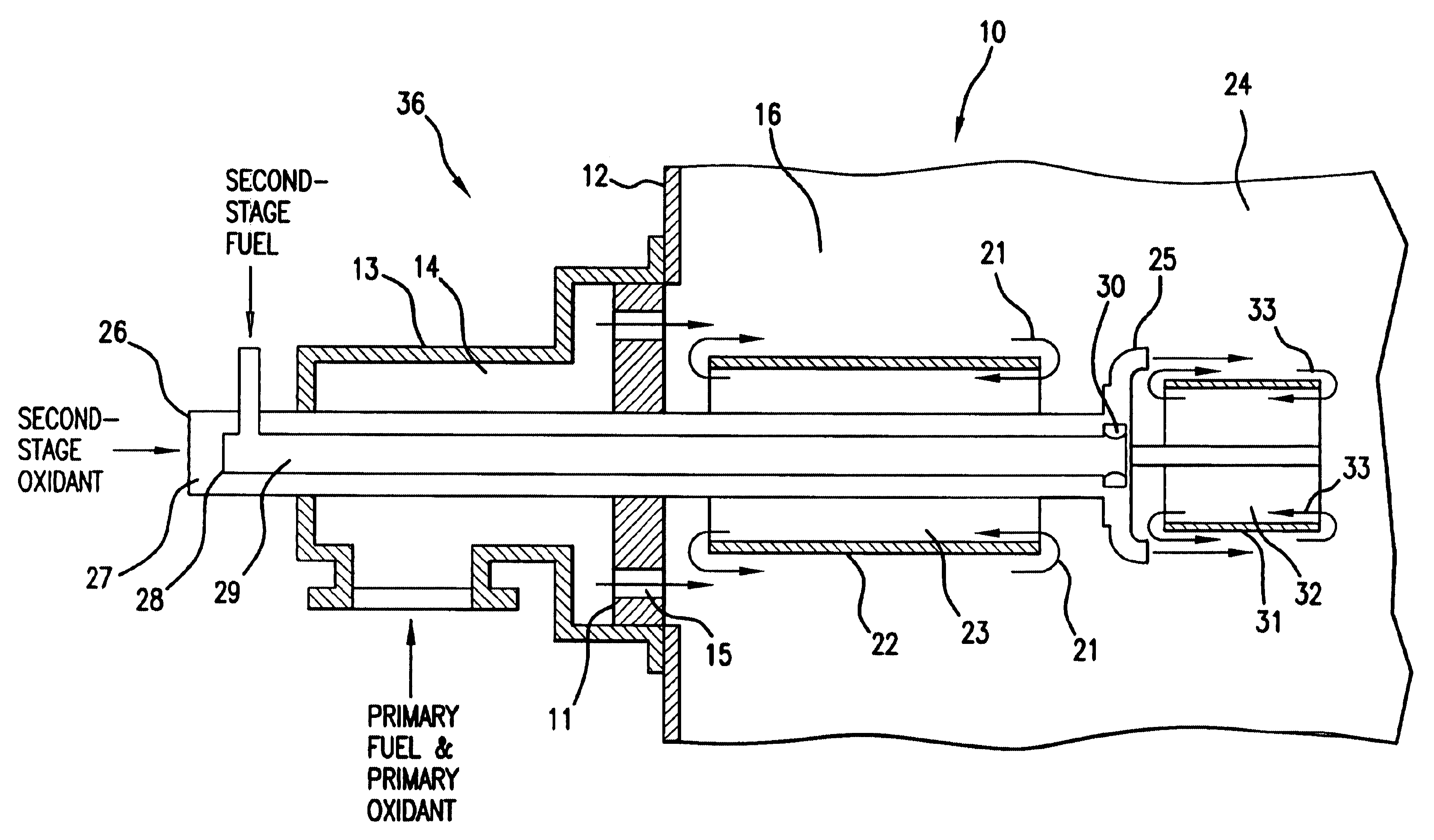
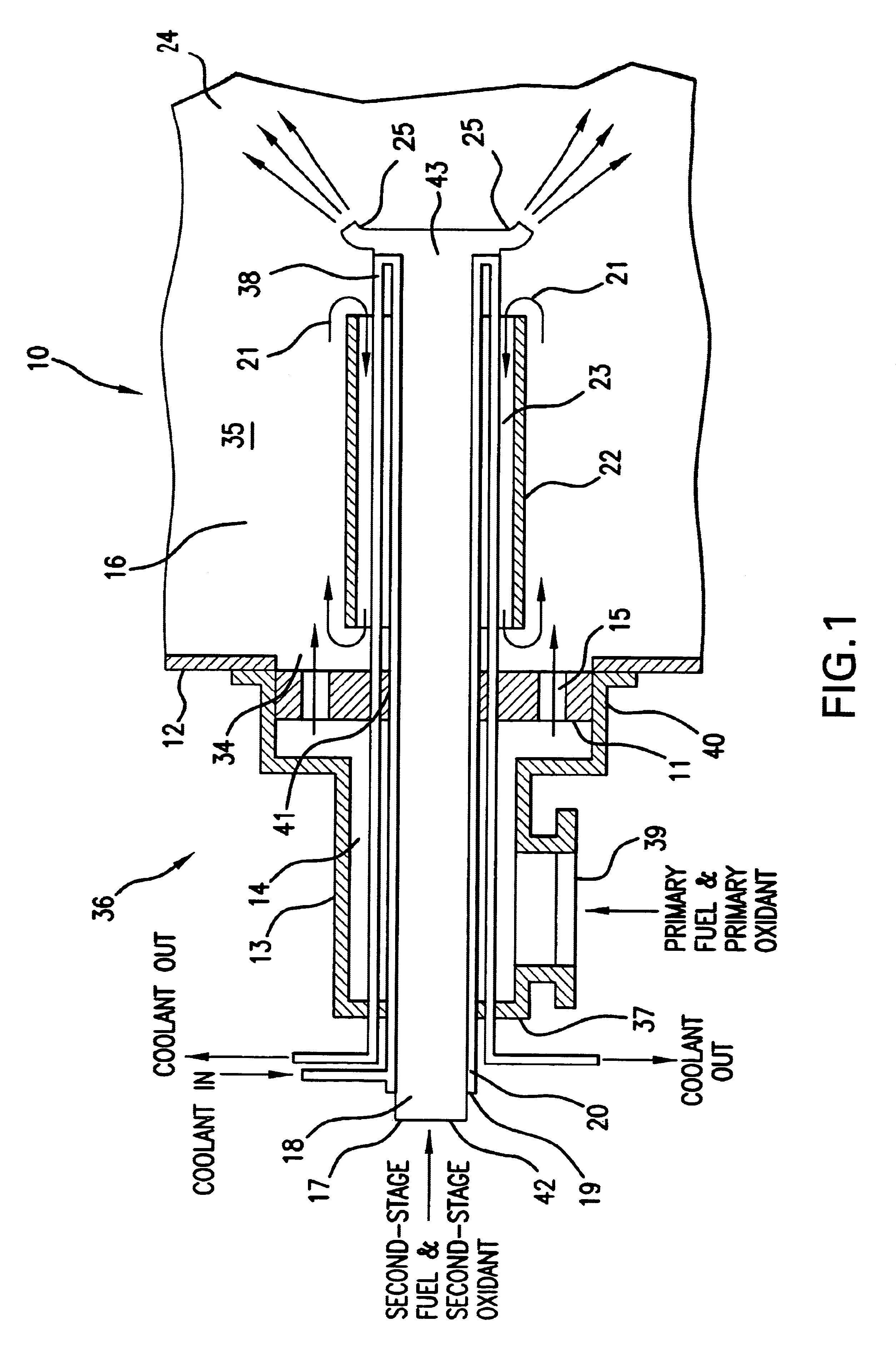
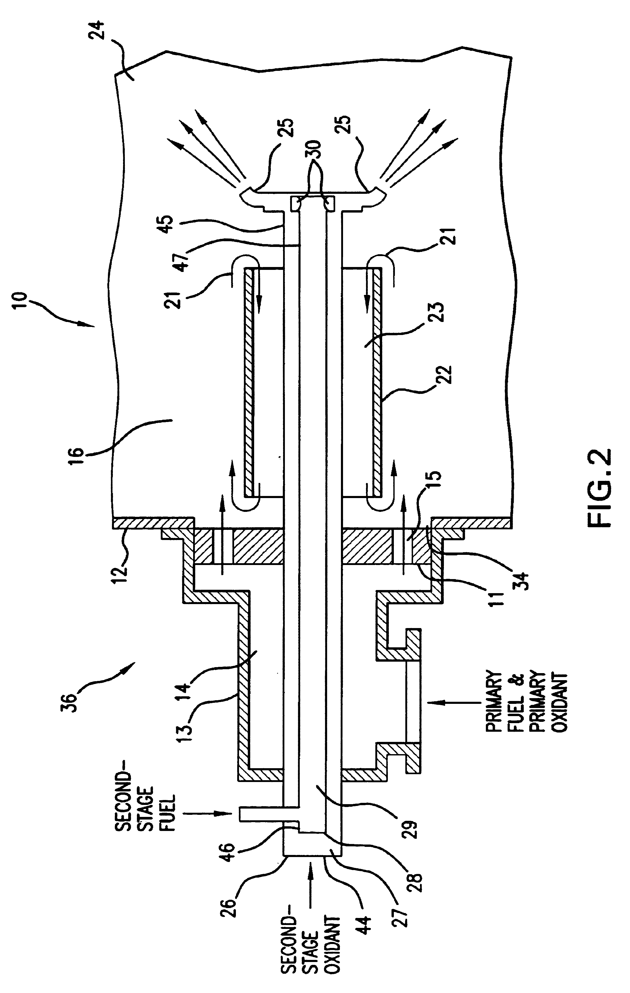
The apparatus of this invention is a burner for boilers and other process heating equipment, such as fluid heaters, furnaces, radiant tubes, and kilns, which are fueled by gaseous and / or liquid fossil fuels, which is designed to reduce the formation of NO.sub.x emission from said boilers and process heating equipment simultaneous with complete combustion of the fuel at low excess oxidant, that is overall stoichiometric ratios preferably not exceeding about 1.25, although higher or lower ratios can be used, if desired. This design results in lower levels of NO.sub.x in the flue gases than comparable burner designs that employ only oxidant staging, that is where fuel is introduced into the burner only in a single stage. Additionally, when compared to oxidant staging designs, this invention is advantageous for retrofit to boilers and ...


PUM


Abstract

A method and apparatus for combustion of a fuel in which a first-stage fuel and a first-stage oxidant are introduced into a combustion chamber and ignited, forming a primary combustion zone. At least about 5% of the total heat output produced by combustion of the first-stage fuel and the first-stage oxidant is removed from the primary combustion zone, forming cooled first-stage combustion products. A portion of the cooled first-stage combustion products from a downstream region of the primary combustion zone is recirculated to an upstream region of primary combustion zone. A second-stage fuel is introduced into the combustion chamber downstream of the primary combustion zone and ignited, forming a secondary combustion zone. At least about 5% of the heat from the secondary combustion zone is removed. In accordance with one embodiment, a third-stage oxidant is introduced into the combustion chamber downstream of the secondary combustion zone, forming a tertiary combustion zone.

Description

1. Field of the InventionThis invention relates to a method and apparatus for staged combustion of a fossil fuel which has the capability of reducing the formation of nitrogen oxides (NO.sub.x) while simultaneously providing substantially complete combustion at low excess oxidant, that is, an overall stoichiometric ratio that does not exceed 1.25, although higher or lower ratios may be employed, if desired. More particularly, this invention relates to a burner for boilers and other process heating equipment such as fluid heaters, furnaces, radiant tubes, and kilns which are fueled by gaseous or liquid fuels, in which the fuel and / or oxidant are introduced in stages, and combustion products are substantially recirculated within the combustion zone.2. Description of Prior ArtConventional combustion of fossil fuels produces elevated temperatures which promote complex chemical reactions between oxygen and nitrogen, forming various oxides of nitrogen as byproducts of the combustion proce...

Claims


Application Information

Patent Timeline
Patent Type & Authority Patents(United States)
IPC IPC(8): F23C6/04F23C9/00F23C6/00
CPCF23C6/04F23C9/006F23C2900/06041F23C2201/30F23C2201/20
Inventor RABOVITSER, IOSIF K.KNIGHT, RICHARD A.CYGAN, DAVID F.NESTER, SERGUEIABBASI, HAMID A.
Owner GAS TECH INST
Why Eureka
Try Eureka