Short-distance locating system

a positioning system and short-distance technology, applied in the direction of transmission, coils, using electrical/magnetic means, etc., can solve the problems of difficult to use the system for positioning within a few centimeters, target must be visible from the telemeter,

Inactive Publication Date: 2003-12-23
COMMISSARIAT A LENERGIE ATOMIQUE ET AUX ENERGIES ALTERNATIVES
View PDF11 Cites 12 Cited by
  • Summary
  • Abstract
  • Description
  • Claims
  • Application Information

AI Technical Summary

Problems solved by technology

However, these systems are limited by the fact that the target has to be seen by the cameras, in other words it must be within the field of vision of these cameras.
Furthermore, this system has a large external infrastructure, in other words it is large; therefore, it is difficult to use it for positioning within a few centimeters.
This technique is used to position an object moving over distances of a few centimeters; but it always has the disadvantage that the target must be visible from the telemeter.
In this case, the link between the object to be positioned and the reference system is mechanical, which has disadvantages in the sense that not all displacements may be authorized, and detection of displacement is not very precise.
However, it is difficult to miniaturize magnetometric sensors for which the precision must be high.
Furthermore, positioning an object in three dimensions makes use of complex calculation algorithms; therefore it is difficult to envisage the use of this type of system to position an object moving within a few centimeters in three dimensions.

Method used


Image

  • Short-distance locating system
  • Short-distance locating system
  • Short-distance locating system

Examples


first embodiment

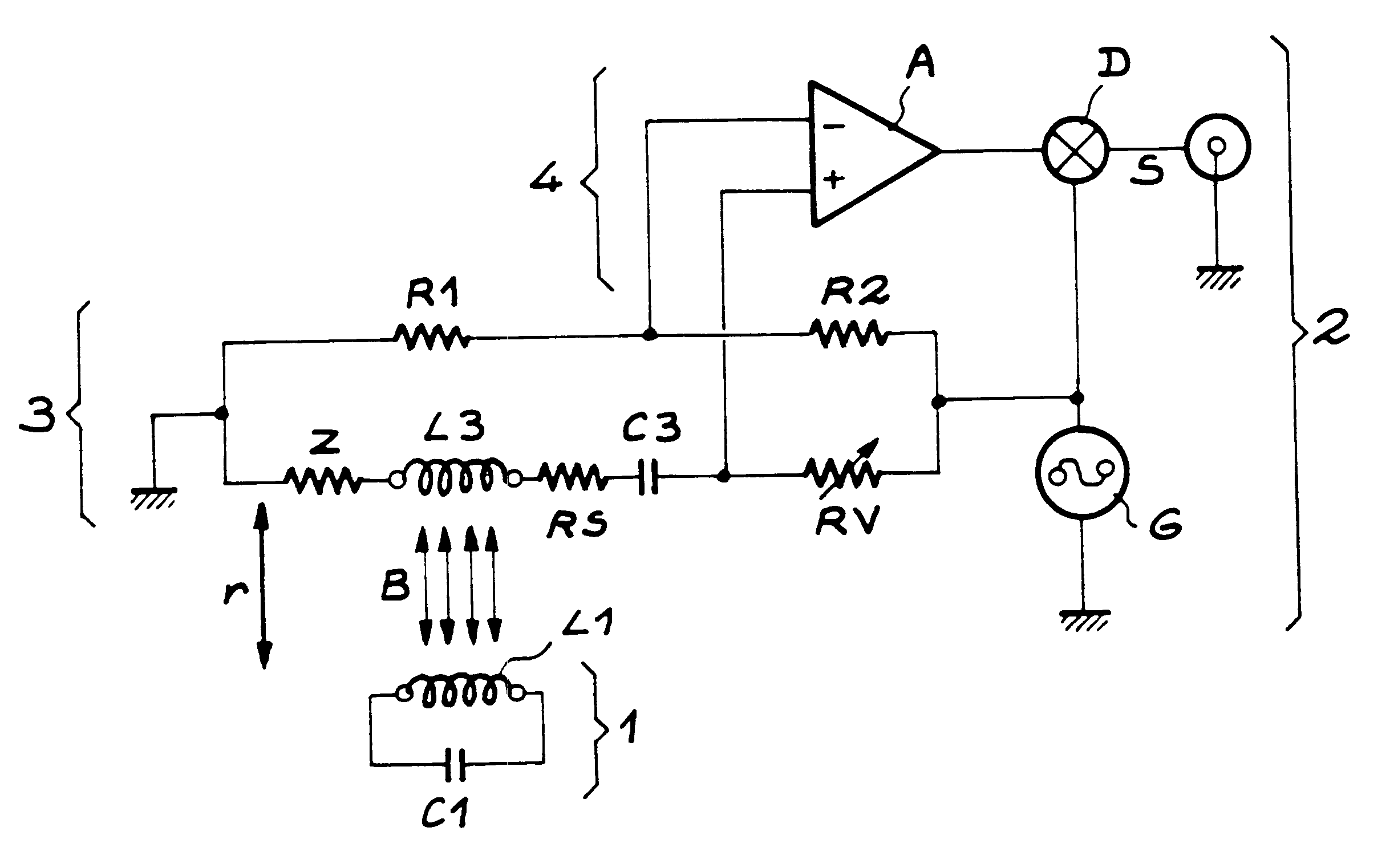
This first embodiment of the probe is illustrated in FIG. 1 which will be described in detail later.

second embodiment

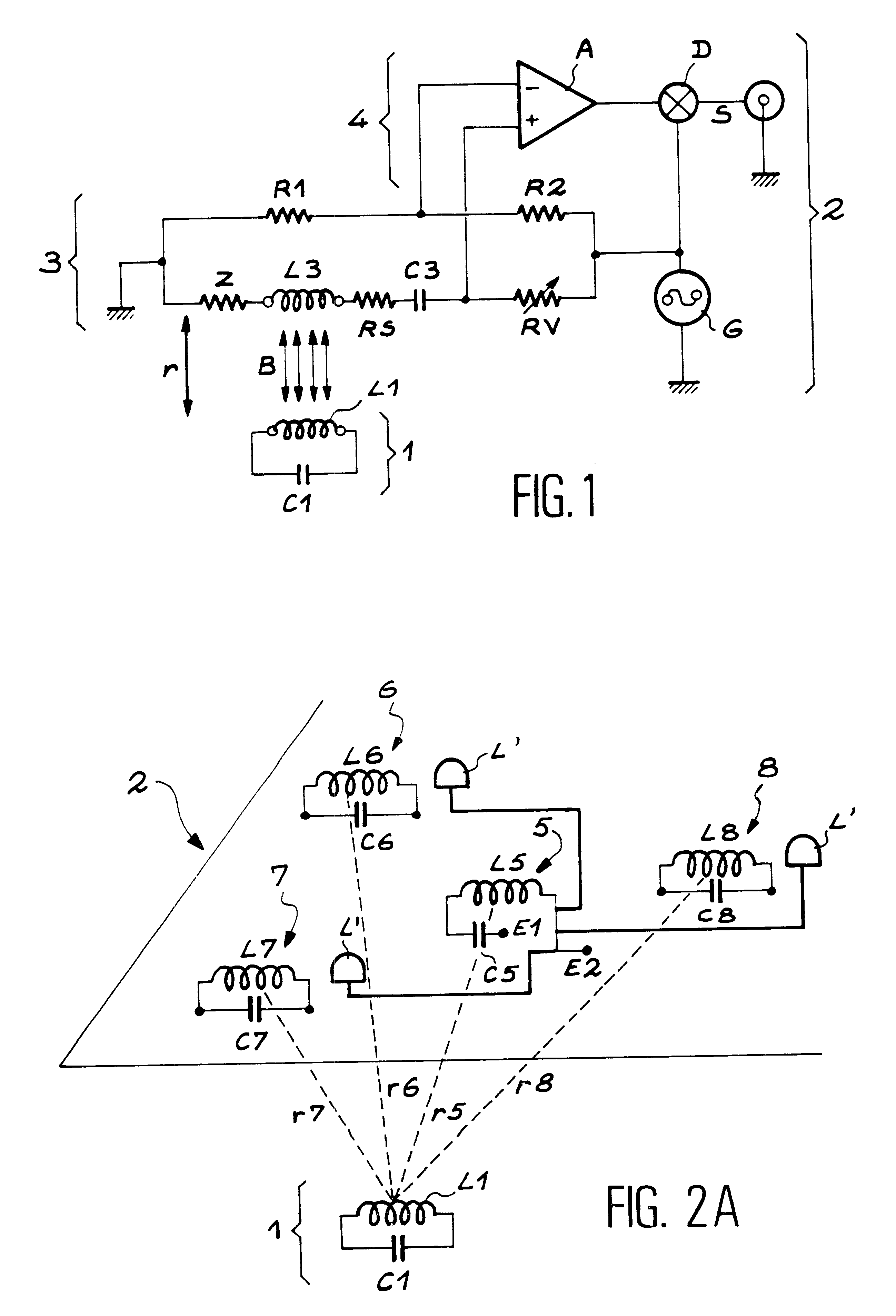
In a second embodiment shown in FIG. 3, the probe comprises two LC resonant circuits. One of these resonant circuits comprises a coil L1' and a capacitor C1' connected in parallel; this circuit receives the magnetic field at frequency f.sub.g. The other circuit comprises a coil L2 and a capacitor C2 connected in series; this circuit transmits a magnetic field with frequency f.sub.e.noteq.f.sub.g. In the example shown in FIG. 3, the reception circuit L1'C1' and the transmission circuit L2C2 are connected to each other through a frequency doubler DF, for example made by a diode bridge. In this case f.sub.e =2.times.f.sub.g.

In order to simplify the description, the remainder of the system according to the invention will be described for a probe conform with the first embodiment, in other words with a single LC circuit.

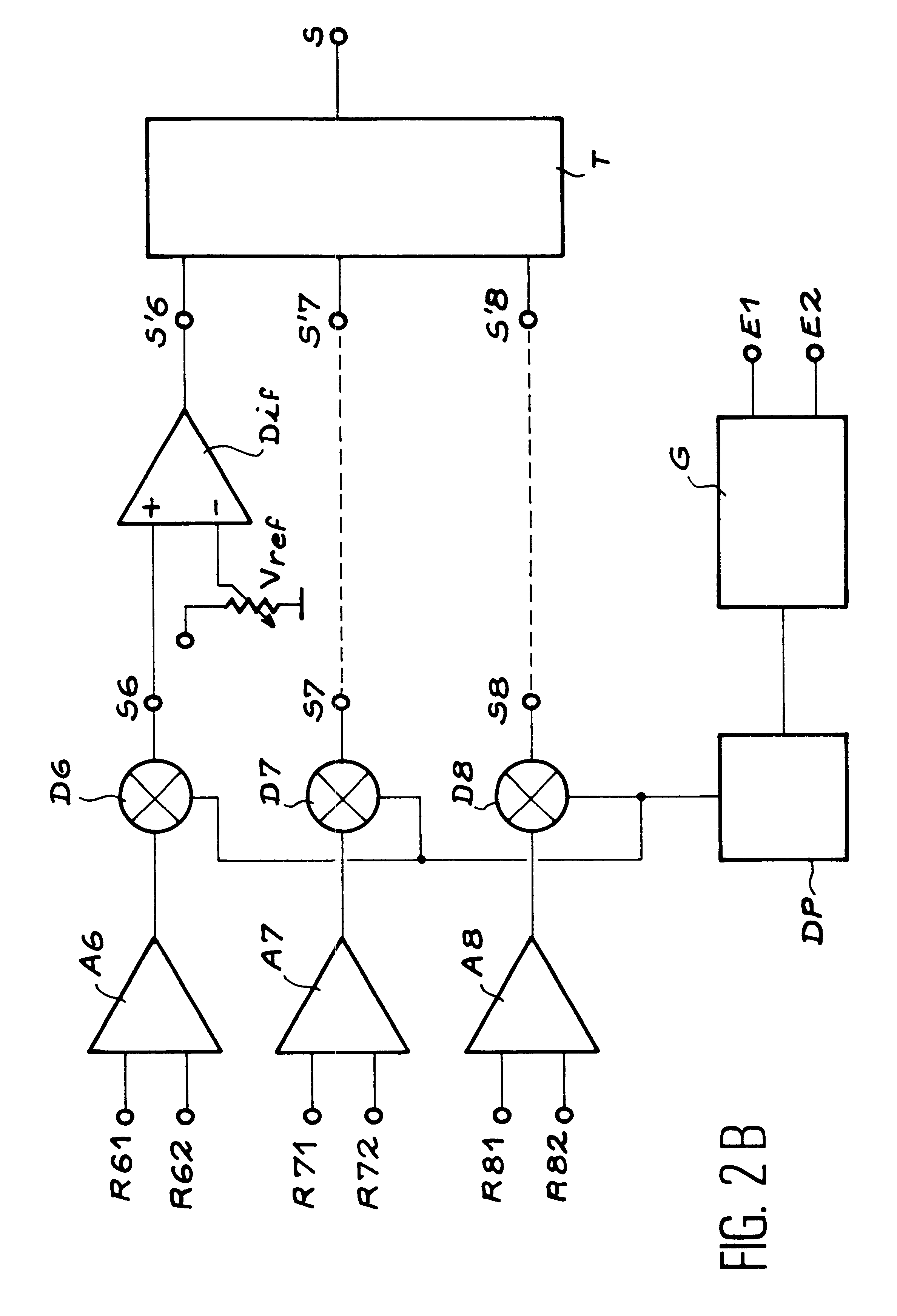
In the system according to the invention, the fixed reference system is equipped with means of transmission of a magnetic field. These transmission means consist of an LC...


PUM


Abstract

A short distance positioning system for a mobile object with respect to a fixed reference system. The mobile object is equipped with a probe, and at least one resonant circuit enabling reception of a magnetic field. A detection and comparison circuit detects the amplitude of the voltage induced at the terminals of the resonant circuit, thereby deducing the displacement of the probe with respect to the reference system.

Description

DOMAIN OF THE INVENTIONThe invention relates to an electromagnetic positioning system for an object free to move with respect to a fixed reference system in which the displacement of the object is of the order of a few centimeters, with a precision better than 1 millimeter.The invention is used for applications in many domains, and particularly in the structural mechanics domain to study deformations of solids subject to stresses, or for protection to monitor the position of an object that could be stolen or in the virtual reality domain to position elements with a man-machine interface.STATE OF THE ARTAt the present time, there are many systems for positioning a mobile object with respect to a fixed reference system. These include some systems that are dedicated solely to short distance positioning, in other words displacement of the object that moves only a short distance with respect to the reference system, in other words of the order of a few centimeters to a few meters.One of ...

Claims


Application Information

Patent Timeline
Patent Type & Authority Patents(United States)
IPC IPC(8): G01B7/004G01D5/20G01B7/00G01D5/12H04B5/00
CPCG01B7/003G01B7/004G01D5/2066H04B5/00G01D5/2073H04B5/0093H04B5/0012H04B5/0087
Inventor DURET, DENIS
Owner COMMISSARIAT A LENERGIE ATOMIQUE ET AUX ENERGIES ALTERNATIVES
Why Eureka
Try Eureka