Apparatus for mixing fluids

a technology of mixing apparatus and fluid, which is applied in the direction of liquid separation auxillary apparatus, centrifugal force sediment separation, feed/discharge of settling tanks, etc. it can solve the problems of increasing the cost of doing business, clogging up the drain lines from the kitchen to the grease trap, and animal fat rendered during the cooking process

Inactive Publication Date: 2003-12-30
HYDROTREAT
View PDF27 Cites 63 Cited by
  • Summary
  • Abstract
  • Description
  • Claims
  • Application Information

AI Technical Summary

Benefits of technology

Another embodiment of a cyclone filter of the present invention has the same housing with the spiral-grooved ring on the outside as the embodiment described above with a narrow annulus added just inside the upper cylinder with the incoming fluid injected in multiple high velocity streams into the annulus to spiral downward to exit the annulus in the lower part of the cylinder away from the outlet as a narrow high velocity stream against the cylinder wall. The narrow annulus eliminates the need for a vortex finder as part of the outlet in many applications.

Problems solved by technology

These surcharges increase the costs of doing business.
In addition to the problem of discharging excessive contaminants to public sewage systems, animal fat rendered during the cooking process can congeal when mixed with cold water and clog up the drain lines from the kitchens to the grease traps.
When this occurs, the businesses may be shutdown and typically require routing out with a rotor cutter driven by a mechanical cable to open the lines.
When the contaminants exceed the capacity of what the bacteria can consume, they must be removed from the grease traps by vacuum trucks, or they are discharged to the public sewer, which can result in surcharges as mentioned above.
Anaerobic bacteria are not as efficient as aerobic bacteria in consuming the contaminants, and they also produce offensive odors in the process of consuming their food.
The offensive odors are prevalent around businesses with grease traps.
Attempts have been made to keep the bacteria alive by bubbling air in grease traps with limited success.
Bubbling air even with the finest diffusers creates a large amount of foam in the grease traps.
Therefore, air injection has been largely limited to short periods of time and to smaller systems.
Therefore, in the food service industry, there is a need for an efficient apparatus and method that can effectively remove particles from wastewater without the problems mentioned above, e.g. incurring surcharges for unsuccessfully meeting contaminant levels, producing offensive odors, requiring the introduction of bubbling air, thus increasing costs, etc.
Detergents and other chemicals used in the wash operation present further difficulties to the discharge problems.
The water is typically reused in the washing part of the wash cycle until it becomes apparent that the quality of the vehicle wash is no longer satisfactory.
The offensive odors are often detected by customers, especially early in the morning when the systems have been shutdown for the night.
The bubbling of air continuously can cause a foaming problem in the sumps.
In addition to the offensive odors, governmental regulations may limit the amount of contaminants that can be discharged into the public sewer systems and totally prevent discharge to the environments.
However, where the cost of water is not a factor and the public sewage system can accept certain contaminants, a complete recycling system may not be cost justified.
These steps may increase the time and money associated with the particle-removal operation.
This may lead to difficulties in certain applications.
However, it has been found that over time, particles concentrate along the inner walls of the apparatus as a result of centrifugal forces and tend to clump together and adhere to the porous walls.
This clump formation or caking impedes the exit of the carrier fluid through the porous walls.
This limits the use of the filters when tangential feeding is not possible, for example.

Method used


Image

  • Apparatus for mixing fluids
  • Apparatus for mixing fluids
  • Apparatus for mixing fluids

Examples


Embodiment Construction

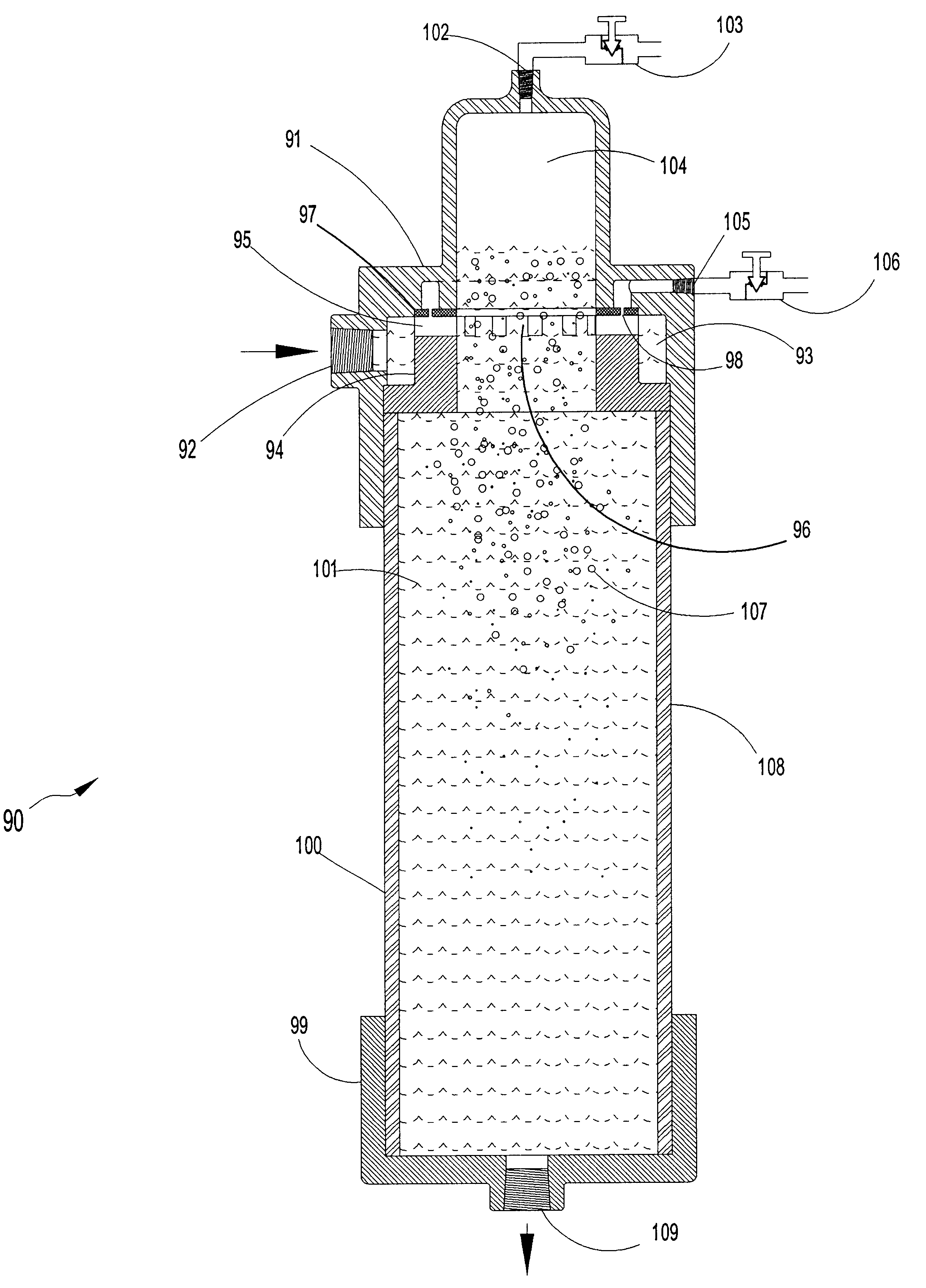
The dynamics of fluid flow generally can be mathematically expressed by conservation of energy, momentum, and impulse. When fluid flows in a curved path, pressure is increased (1) with the radial distance from the center of rotation outward, (2) with the angular velocity of the fluid, and (2) with the unit mass of the fluid. A fluid may rotate in a closed vessel by applying an external force resulting in a forced vortex. If the entire body of fluid rotates together with all particles rotating in a concentric circle, a cylindrical vortex is formed. If radial flow is combined with the circular flow, a forced spiral vortex results. The forced spiral vortex can be used for separation of fluids by density, separation of suspended solids from fluids also by density, and the mixing of various fluids.

Illustrative embodiments of the invention are described below as they might be employed in the use of methods and apparatus for separating fluids, mixing fluids, and separating solids from flui...


PUM

PropertyMeasurementUnit
cross-sectional areaaaaaaaaaaa
velocityaaaaaaaaaa
velocityaaaaaaaaaa

Abstract

An apparatus is provided for separation of suspended solid particles from fluids, for separation and mixing of fluids, and for dissolving gases in aqueous fluids. The apparatus employs a grooved ring to divide the fluid stream and impart a high velocity on each of the divided or sub-streams. A grooved ring with any number of grooves that may be spiral in shape is used to create a high velocity circular motion on a divided stream for separation of suspended solid particles by centrifugal force in a cyclone filter and for saturation of liquid with gases in a fluid mixer where gases are introduced through a diffuser. A grooved ring with any number of grooves that may be radial is used in a fluid mixer to divide a stream of fluid, produce a high velocity flow through each groove, introduce a second fluid through an orifice into the first fluid flowing through each groove, and direct the fluid mixture to a center impact zone where the various streams collide to complete the mixing.

Description

1. Field of the InventionThe invention relates to methods and apparatus of physical separation of solids from fluids or for mixing two fluids. More specifically, the invention relates to methods and apparatus for separating solids from fluids and mixing fluids by using a ring having a plurality of grooves through which fluid passes. The methods and apparatus of the present invention are particularly suitable for use in treatment of aqueous fluids, such as water and wastewater, by dynamic separation of contaminants to be removed and by dynamic mixing of treating agents to be added as part of treatment.2. Description of the Related ArtCommercial and industrial processes currently employ countless operations involving mixing of fluids (liquids with liquids, gases with liquids, and gases with gases) or separation of fluids or solids from other fluidsFor example, excessive contaminants must be removed from the wastewater of food service institutions (restaurants, cafeterias, hospitals, e...

Claims


Application Information

Patent Timeline
Patent Type & Authority Patents(United States)
IPC IPC(8): B01D21/24B03D1/14E21B43/34E21B43/12E21B43/16B01D17/035B01D17/038B01D17/12B01D65/00
CPCB01D21/2433B01D21/245B03D1/1456B03D1/1418B03D1/1431
Inventor ARNAUD, JOHNNY
Owner HYDROTREAT
Why Eureka
Try Eureka