Gutter cover device

a gutter and cover technology, applied in the field of gutter covers, can solve the problems of water flowing over the edge of the gutter, deterioration of the gutter, etc., and achieve the effect of improving the flow of water

Inactive Publication Date: 2004-01-06
SOUTHEASTERN METALS MFG
View PDF17 Cites 45 Cited by
  • Summary
  • Abstract
  • Description
  • Claims
  • Application Information

AI Technical Summary

Benefits of technology

The gutter cover device of the present invention overcomes the disadvantages of the prior known covers by incorporating a combination of surface textures and coatings to improve the flow of the water to the cover surface thereby ensuring delivery of the water into the gutter.
In order to improve the flow of the water to the panel so that it travels around the arcuate nose and into the gutter, a combination of coatings, substrates and textures are applied. The coatings and substrates aid in the release of dirt from the panel, increase the resistance to fading and staining while also improving the flow of the water across the panel. By incorporating a textured surface, the flow of the water is slowed and spread across an increased surface area of the panel ensuring that it will flow into the gutter while expelling debris over the gutter.
Possible substrate textures include a stucco dimpled, pimpled, or diamond pattern embossed in the material. Possible coatings for the panel include a polyester based coating, a silicone polyester based coating and a polyvinylidine fluoride based coating. The coatings may be used in conjunction with the substrate textures to improve water flow. Certainly, the coating material could be used to create the texture. The surface coating formulation and texture are used to improve the fluid flow across the cover. A formulation is chosen which is resistant to staining and the build-up of dirt or organic material along the arcuate nose of the cover.

Problems solved by technology

Such debris can clog the gutter preventing water from being properly diverted and over time can cause deterioration of the gutter.
However, it has been determined that increased flow rates, such as those that would be found on roofs with high pitches, can sometimes result in the water flowing over the edge of the gutter.

Method used


Image

  • Gutter cover device
  • Gutter cover device
  • Gutter cover device

Examples


Embodiment Construction

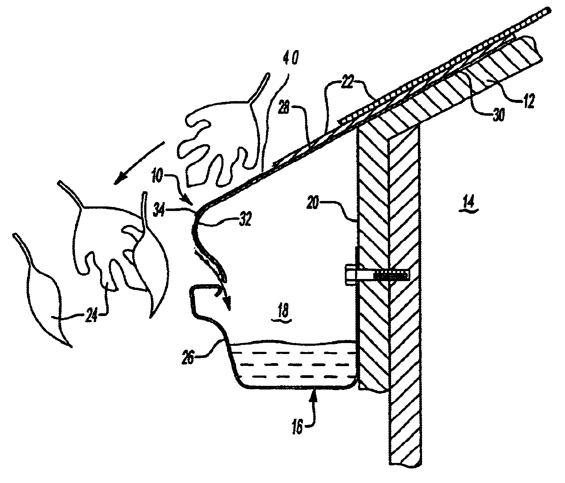
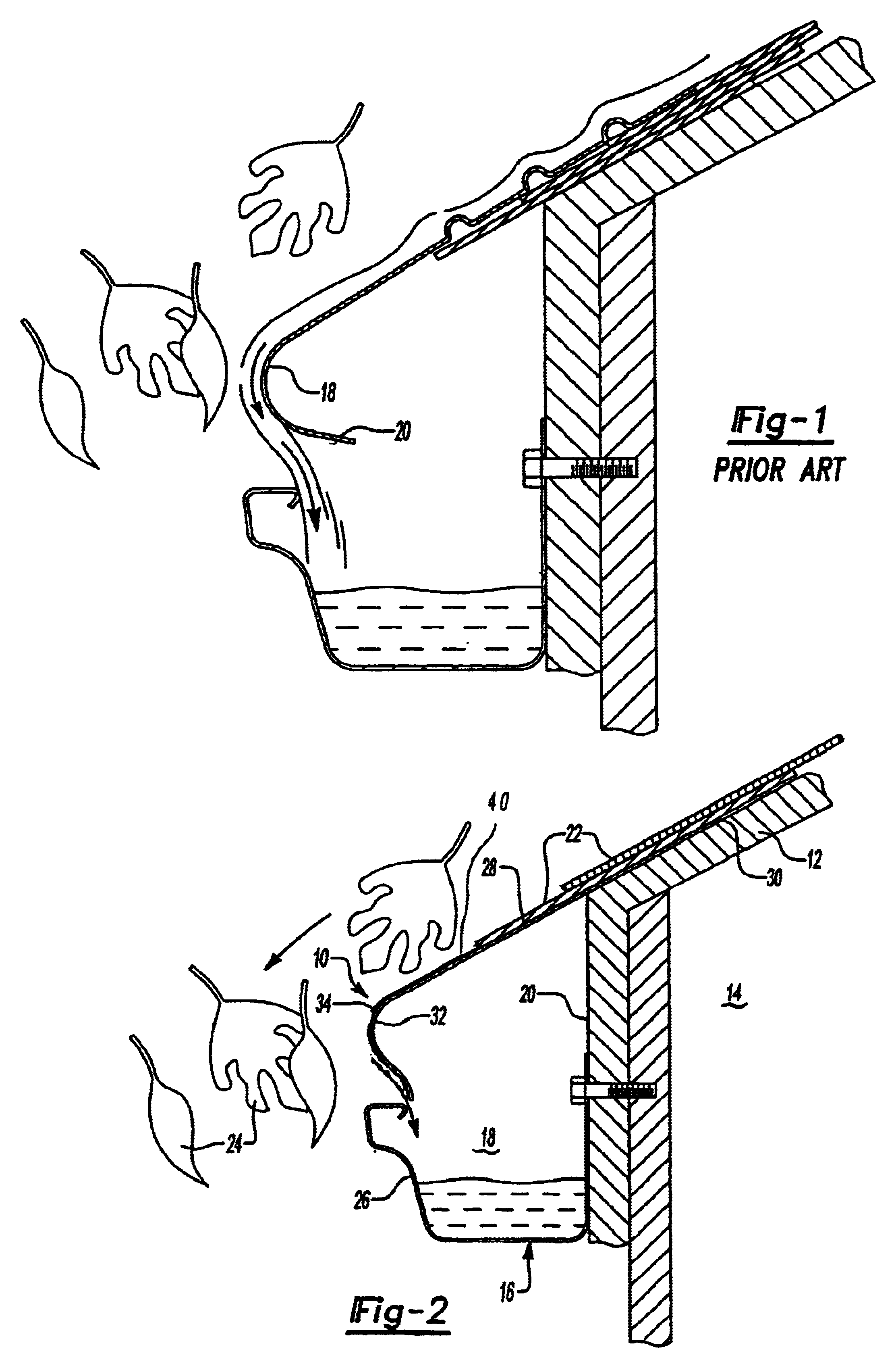
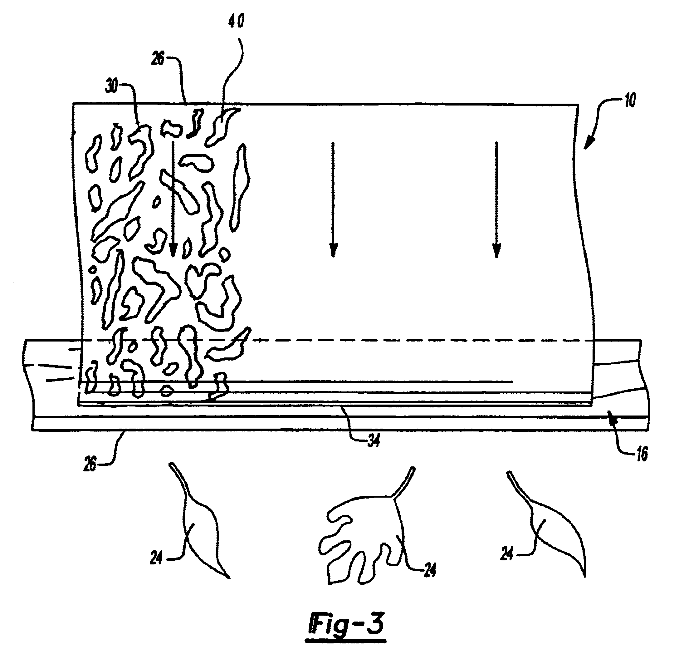
Referring to FIGS. 2 and 3, there is shown a gutter cover 10 embodying the present invention attached to a roof 12 of a building 14 proximate a gutter 16 mounted along the periphery of the roof 12. The gutter 16 is adapted to collect rainwater and similar fluid runoff from the roof 12 and direct it to downspouts (not shown) for delivery to runoff areas. As is well known, the gutter 16 forms a trough 18 and is mounted to a fascia 20 of the building 14 just below the edge of the roof 12. The roof 12 will be covered with a plurality of shingles 22 to protect the building 14 against leaks.

The gutter cover 10 of the present invention is a device designed to slow the flow of water thereby improving flow to ensure the runoff is directed into the gutter 16 while expelling debris 24 such as leaves and twigs outwardly over the front edge 26 of the gutter 16. The cover 10 includes a substantially planar upper portion 28 having an upper longitudinal edge 30 and an arcuate nose 32 forming a lowe...


PUM

PropertyMeasurementUnit
surface tensionaaaaaaaaaa
flow ratesaaaaaaaaaa
resistanceaaaaaaaaaa

Abstract

A gutter cover for directing the flow of rainwater from a building roof into a gutter mounted to the peripheral edge thereof while preventing debris such as leaves and twigs from entering and clogging the gutter. The cover is secured to the roof of the building such that rainwater flowing down the shingles will flow across the cover at the bottom roof line. A lower end of the cover has an arcuate nose disposed substantially above the outer edge of the gutter. The surface of the gutter is treated with one or more combinations of coatings and / or substrate textures to slow the flow of water while improving flow to the cover surface. Rainwater will flow around the arcuate nose into the gutter while debris carried by the rainwater is expelled outwardly over the edge of the gutter.

Description

I. Field of the InventionThis invention relates to a cover to prevent debris from entering a rain gutter while directing fluid flow from a roof into the gutter for diversion to the ground and, in particular, to a gutter cover having a unique surface formulation and texture to assure diversion and spreading of the fluid flow along the cover surface into the gutter while resisting staining and the build-up of dirt.II. Description of the Prior ArtA variety of devices have been employed to prevent debris such as leaves and twigs from entering a gutter system. Such debris can clog the gutter preventing water from being properly diverted and over time can cause deterioration of the gutter. The prior known gutter covers have included everything from simple screens placed over the top of the gutter to complex devices designed to slow the water flow to ensure entry into the gutter while expelling debris over the outside edge of the gutter.One of the best operating gutter covers is the Gutter...

Claims


Application Information

Patent Timeline
Patent Type & Authority Patents(United States)
IPC IPC(8): E04D13/076E04D13/04
CPCE04D13/076Y10T428/24355Y10T428/14Y10S428/906Y10T428/31823Y10T428/31678Y10T428/31815
Inventor BAHROOS, GOBINDEISENBRAUN, DAVIDFORD, DANIELGIBBONS, STEPHENKATSAMBERIS, DIMITRISMAIELLO, DENNIS
Owner SOUTHEASTERN METALS MFG
Why Eureka
Try Eureka