Subsea well production facility

a production facility and subsea well technology, applied in the direction of sealing/packing, mixing, borehole/well accessories, etc., can solve the problems of increasing the energy requirements of the reservoir and the size of the pump, increasing the risk of hydrates, and increasing the demand for chemicals to control hydrates

Inactive Publication Date: 2004-01-06
ABB OFFSHORE SYST INC
View PDF26 Cites 54 Cited by
  • Summary
  • Abstract
  • Description
  • Claims
  • Application Information

AI Technical Summary

Problems solved by technology

Transporting water from a subsea well decreases the transportation efficiency and increases the reservoir energy requirements and size of the pump (if used) required to pump the well fluid from the subsea well to a processing facility or to a collection manifold.
Further, water in the hydrocarbon stream increases the risk of hydrates and the demand for chemicals to control hydrates."
Additionally, the water with residual hydrocarbons must be reinjected into a subsea well because it is too contaminated to be released or dumped to sea.
Furthermore, reinjecting water into a subsea well can be expensive and is not always feasible; subject to the availability of a suitable subsea reservoir.

Method used


Image

  • Subsea well production facility
  • Subsea well production facility
  • Subsea well production facility

Examples


Embodiment Construction

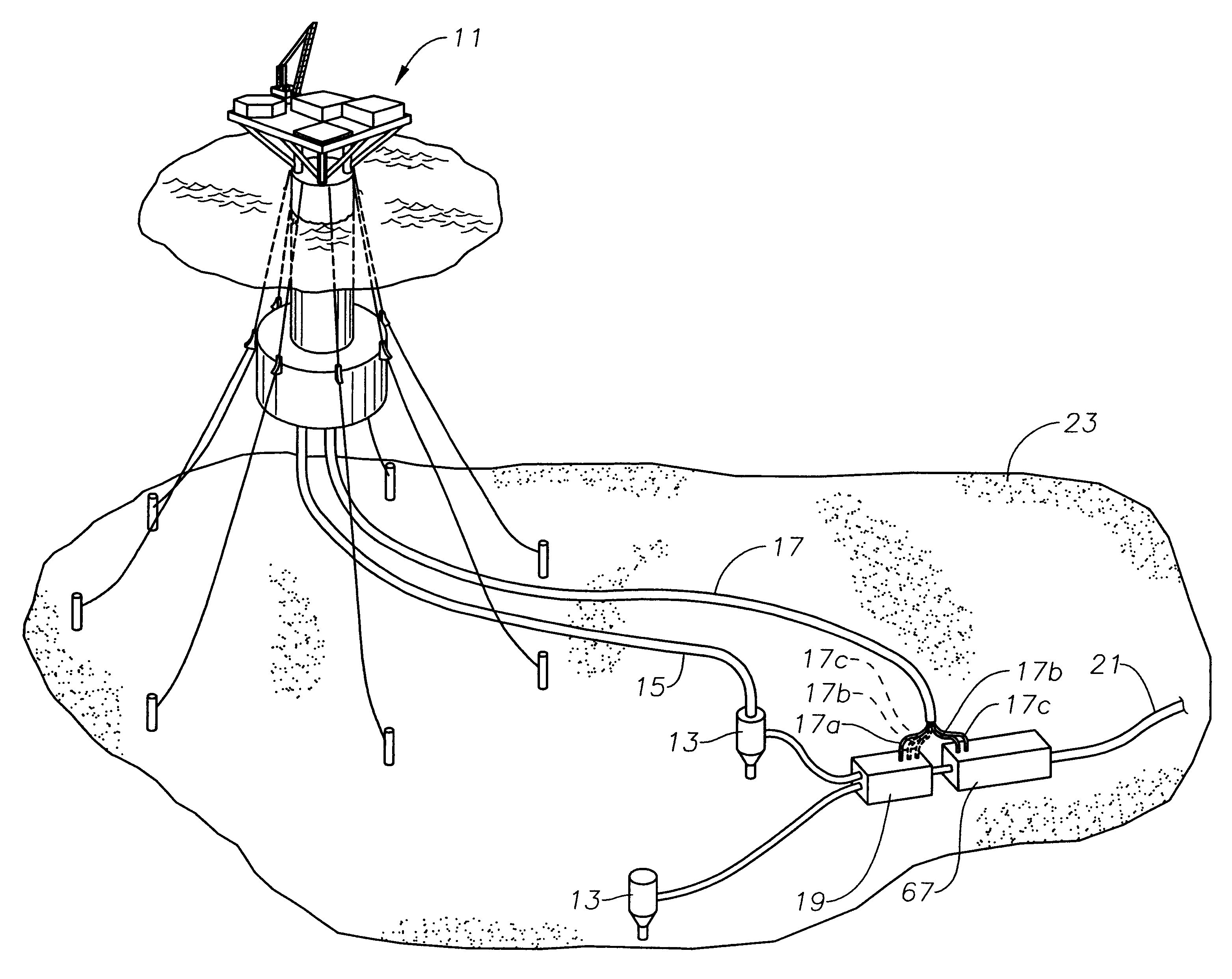
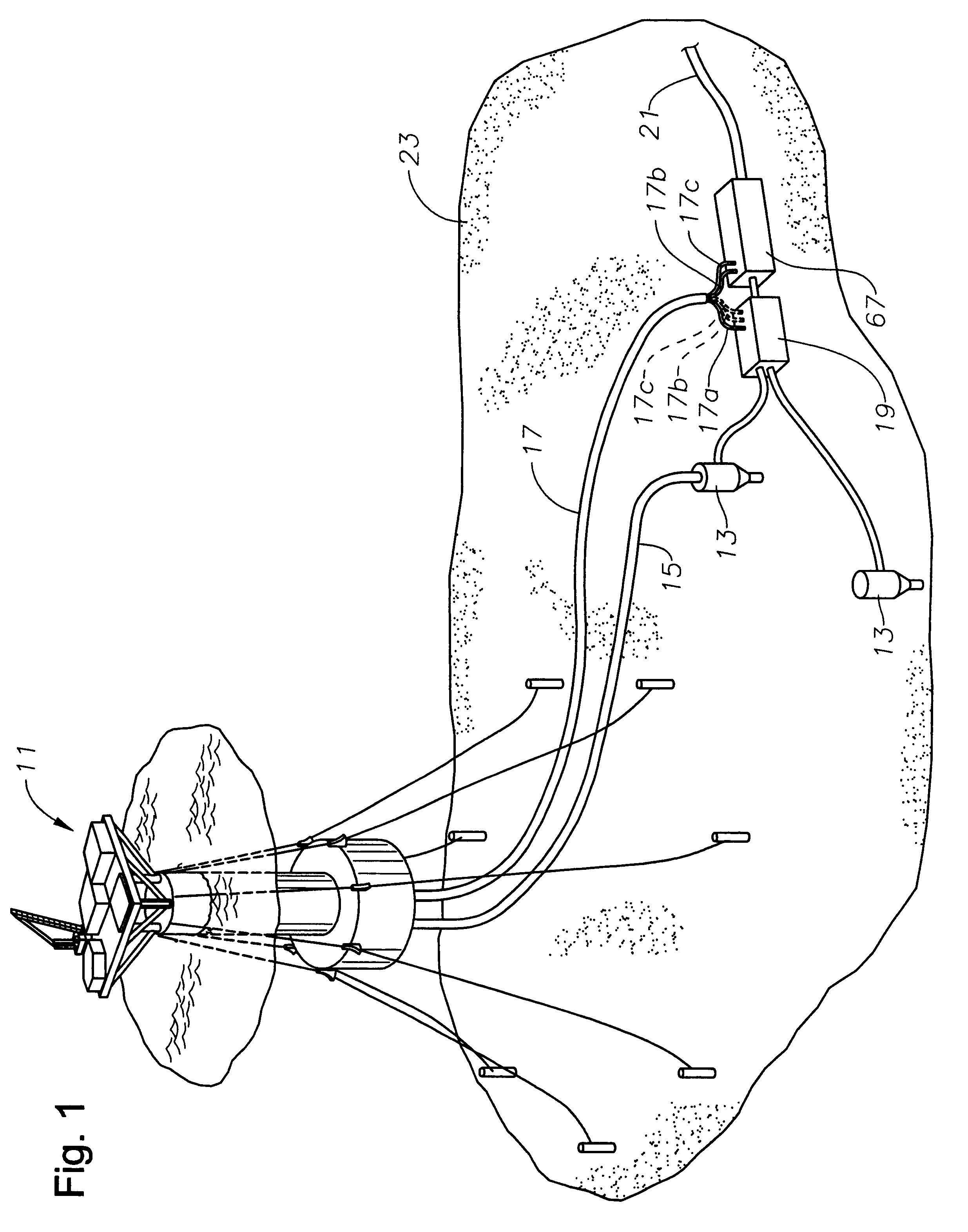
Referring to FIG. 1, a floating vessel or buoy 11 for subsea wells connects to one or more subsea wellheads 13 of subsea wells by risers 15 and 17. Riser 15 is an optional riser capable of providing a passageway for intervention, communication, and control of the subsea well. In the preferred embodiment, buoy 11 is a floating production buoy, but those skilled in the relevant art will readily appreciate that buoy 11 could also be a tanker. Riser 17 is an optionally insulated and heated riser for the transportation of produced water from a subsea separator 19 to floating support buoy 11, and for the transportation of oil and gas from floating support buoy 11 to a production flow line 21 that runs along the ocean floor 23 to a production platform (not shown). Electricity for heating riser 17 is optionally generated by burning gas from subsea well that is conveyed to buoy 11 by riser 17. Riser 17 has at least two separate flow lines 17a and 17b.

Subsea separator 19 may be a free-water k...


PUM


Abstract

A method and system for separating and treating water produced from a subsea well includes separating the water subsea, and then separating the water from residual hydrocarbons on a surface vessel. The water treated at the surface, can be dumped to sea or injected into other subsea wells. The residual hydrocarbons separated on the vessel can be conveyed subsea for transportation to a processing facility along with hydrocarbons from the subsea separator. Also, the residual hydrocarbons from the surface separator can be used to fuel gas powered equipment in order to drive other equipment or to generate electricity for the vessel.

Description

1. FIELD OF THE INVENTION1. This invention relates in general to offshore drilling and production equipment, and in particular for treating produced water from a subsea well.2. BACKGROUND OF THE INVENTIONWell fluid produced from a subsea well typically includes liquid hydrocarbons or oil, gaseous hydrocarbons or natural gas, and water. Transporting water from a subsea well decreases the transportation efficiency and increases the reservoir energy requirements and size of the pump (if used) required to pump the well fluid from the subsea well to a processing facility or to a collection manifold. Typically the processing facility is either on a platform or on land. Further, water in the hydrocarbon stream increases the risk of hydrates and the demand for chemicals to control hydrates."There is a pilot program in which a subsea separator is placed adjacent a subsea well that separates the produced water from the well fluid. The produced water, which typically includes some residual gas...

Claims


Application Information

Patent Timeline
Patent Type & Authority Patents(United States)
IPC IPC(8): E21B43/00E21B43/017E21B43/34E21B43/36E21B43/40
CPCE21B43/017E21B43/36E21B43/40E21B43/0175E21B43/35
Inventor ANDERSON, CLAY F.ALLEN, JOHN
Owner ABB OFFSHORE SYST INC
Why Eureka
Try Eureka