Hydraulic vibration-damping support including a clip-on decoupling flap

a technology of vibration-damping support and clip-on decoupling flap, which is applied in the direction of machine supports, shock absorbers, jet propulsion mountings, etc., can solve the problem of relatively difficult implementation of the assembly process, and achieve the effect of simple manufacturing

Inactive Publication Date: 2004-01-13
HUTCHINSON SA
View PDF21 Cites 11 Cited by
  • Summary
  • Abstract
  • Description
  • Claims
  • Application Information

AI Technical Summary

Benefits of technology

A particular object of the present invention is to mitigate that drawback.
By means of these provisions, the decoupling flap is positioned properly relative to the gratings of the rigid partition, which makes it possible to give the flap and the gratings any outline, and in particular an outline that is not symmetrical about an axis.
Finally, it should be noted that the two fastening members of the decoupling flap are clipped into two liquid-passing holes, so that it is no longer necessary to provide dedicated clipping holes for the sole purpose of clipping the decoupling flap. The gratings of the rigid partition are thus simpler to manufacture.

Problems solved by technology

This is even more important since the assembly process in question is usually performed in a bath of liquid to guarantee that the hydraulic vibration-damping support is filled properly with said liquid, so that said assembly process is relatively difficult to implement.

Method used


Image

  • Hydraulic vibration-damping support including a clip-on decoupling flap
  • Hydraulic vibration-damping support including a clip-on decoupling flap
  • Hydraulic vibration-damping support including a clip-on decoupling flap

Examples


Embodiment Construction

In the various figures, like references designate identical or similar elements.

It should be noted that, in the following description, the terms "top", "bottom", "upwards", and "downwards" are given merely to make it easier for the reader to understand, with reference to the example shown in the drawings, but that they are in no way limiting.

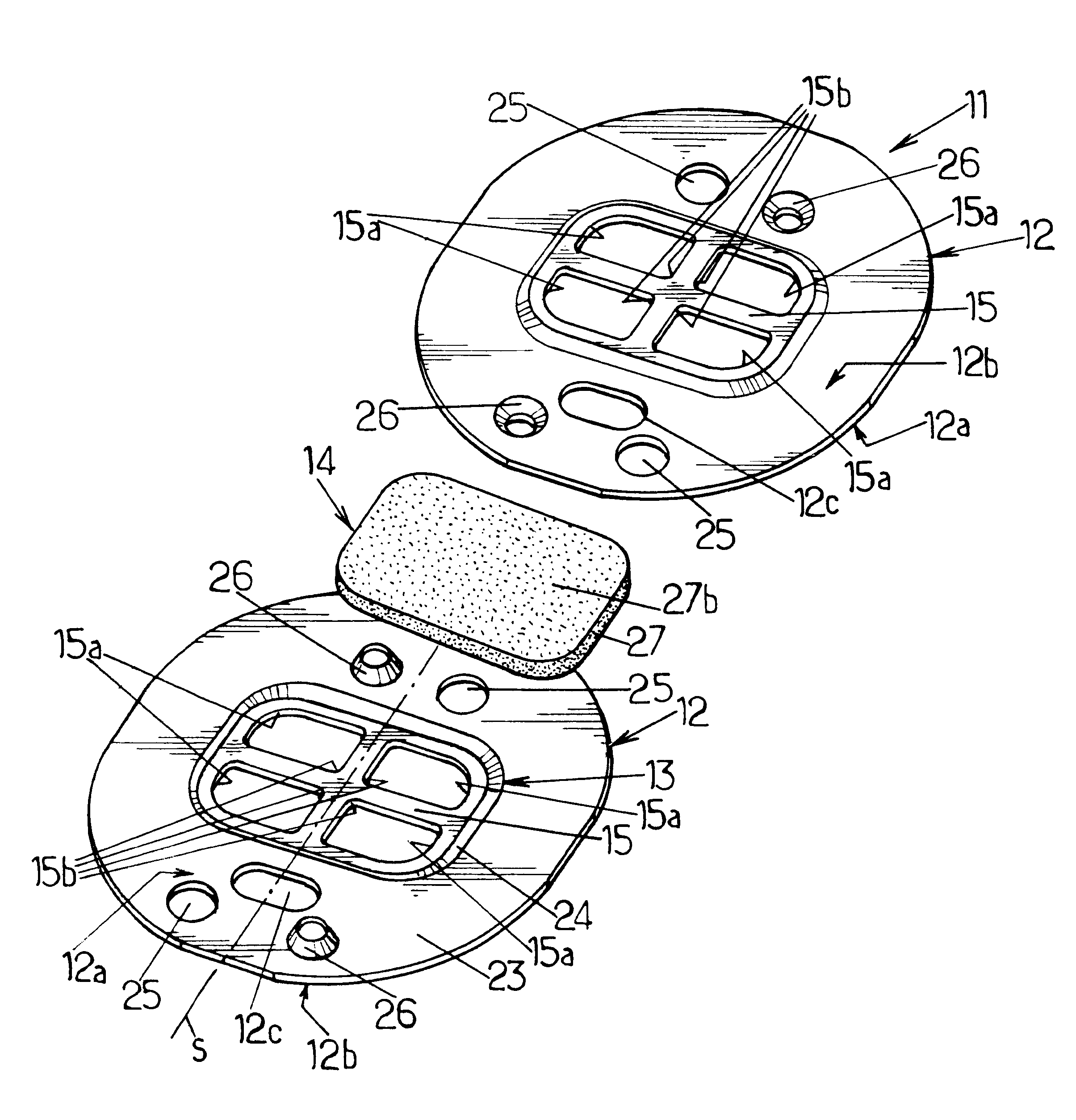
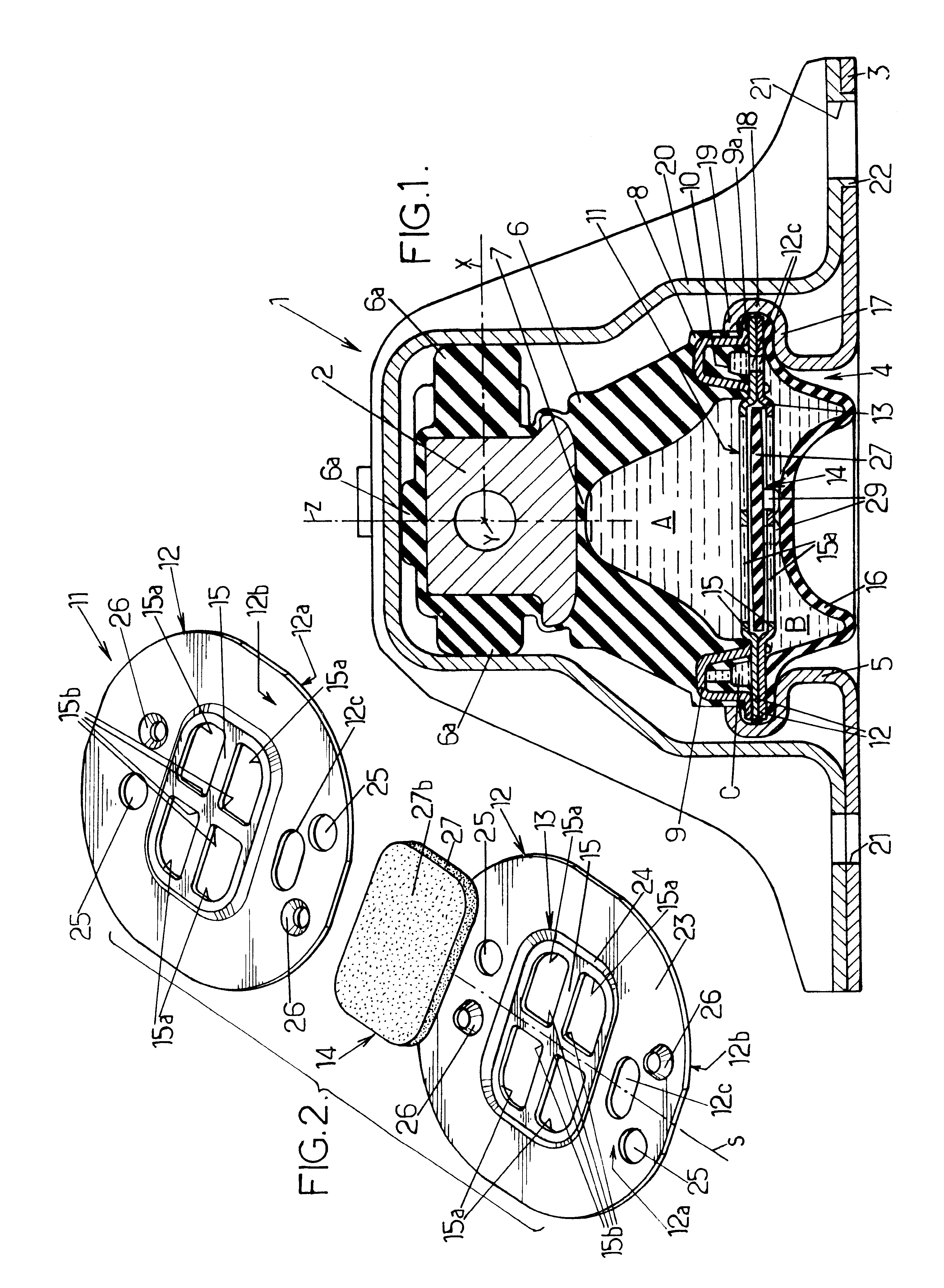
FIG. 1 shows a vibration-damping support 1 which comprises:

a first rigid metal strength member 2 which, in the example shown, extends longitudinally along a horizontal axis Y, and which is designed to be fixed to the engine-and-gearbox unit of a vehicle, for example;

a second rigid metal strength member 3 which is designed to be fixed to the body of the vehicle, for example; in the example in question, the second strength member is in the form of a horizontal plate of sheet metal provided with a central opening 4 having an annular rim 5 that extends upwards;

an elastomer body 6 which is bell-shaped and which extends about a vertical axis Z between...


PUM


Abstract

A hydraulic vibration-damping support comprising two strength members interconnected by an elastomer body which defines a working chamber communicating with a compensation chamber via a constricted passage. The two hydraulic chambers are separated from each other by a rigid partition formed by two gratings disposed one on the other, and a decoupling flap is mounted with a small amount of clearance between the gratings. The decoupling flap is provided with two catches that are clipped onto one of the gratings.

Description

The present invention relates to hydraulic vibration-damping supports including clip-on decoupling flaps and serving, for example, for mounting the engine-and-gearbox unit of a vehicle on the body of the vehicle.More particularly, the invention relates to a hydraulic vibration-damping support designed to be interposed between two rigid elements (e.g. an engine-and-gearbox unit of a vehicle and the body of said vehicle) for damping and interconnection purposes, said support comprising:two rigid strength members designed to be connected to respective ones of the two rigid elements to be interconnected;an elastomer body connecting together the two strength members;a working chamber filled with liquid and defined in part by the elastomer body;a flexible elastomer wall which is secured to the second strength member;a compensation chamber filled with liquid and defined in part by the flexible elastomer wall;a constricted passage filled with liquid and which puts the working chamber into c...

Claims


Application Information

Patent Timeline
Patent Type & Authority Patents(United States)
IPC IPC(8): F16F13/10F16F13/04F16F13/14B60K5/12F16F13/18
CPCF16F13/106
Inventor DESMOULINS, MICKAELMONNEAU, JEAN-PIERRE
Owner HUTCHINSON SA
Why Eureka
Try Eureka